724-746-5500 | blackbox.com
Page 27
SOFTWARE UPGRADE
B. INTERFACE PINOUTS
B.1 LINE PORT
B.1.1 RJ-45
• Pin 4: Tip
• Pin 5: Ring
• Pins 1, 2, 3, 6, 7, 8: no connection
B.2 ETHERNET PORT
B.2.1 RJ-45
SOCKET
10/100B
ASE
-T
• Pin 1: TX+
• Pin 2: TX-
• Pin 3: RX+
• Pin 6: RX-
NOTE: Pins not listed are not used.
724-746-5500 | blackbox.com
Page 2
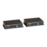
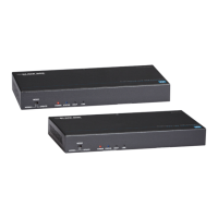
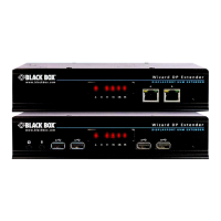
Black Box Long Range Ethernet Extender
TABLE OF CONTENTS
1. GENERAL INFORMATION .........................................................................9
1.1 Features ..............................................................................................9
1.2 Description.......................................................................................... 9
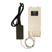
1.3 Power Input Connector ..................................................................... 10
1.3.1 External AC universal power supply. .................................... 10
1.3.2 External 48 VDC power supply............................................. 11
2. CONFIGURATION..................................................................................... 11
2.1 Hardware (DIP-Switch) Configuration ...............................................11
2.2 Configuring the DIP-Switches........................................................... 12
2.3 DIP Switch Settings .......................................................................... 13
2.3.1 DIP switch settings: Data Rate .............................................13
2.4 Ethernet Management Port............................................................... 16
2.4.1 LB512A-KIT Status ...............................................................16
2.4.2 Help Commands ................................................................... 17
2.4.3 Example command line interface session ............................ 17
3. INSTALLATION ......................................................................................... 17
3.1 Connecting the Line Interface ...........................................................18
3.2 Connecting the Ethernet Interface .................................................... 19
3.3 Connecting Power ............................................................................ 19
3.3.1 External AC universal power supply .....................................19
3.3.2 DC Power ............................................................................. 19
4. OPERATION.............................................................................................. 20
4.1 Power-up ..........................................................................................20
4.2 LED Status Monitors......................................................................... 20
4.2.1 Power (Green) ......................................................................21
4.2.2 Link (Green).......................................................................... 21
4.2.3 ETH Activity (Green)............................................................. 21
4.2.4 ETH Link (Green).................................................................. 21
5. SOFTWARE UPGRADE............................................................................ 22
A. SPECIFICATIONS..................................................................................... 23
A.1 Line Rate ..........................................................................................23
A.2 Ethernet Interface .............................................................................23
A.3 Status LED ........................................................................................23
A.3.1 Power (Green) .....................................................................23
A.3.2 Link (Green) ........................................................................23
A.3.3 ETH Activity (Green) ...........................................................23
A.3.4 ETH Link (Green) ................................................................23
 Loading...