The Black Star Jupiter 500 is a versatile function generator designed for a wide range of applications, from audio testing to I.F. alignment and chart recorder testing. It offers a broad frequency range, multiple waveform outputs, and various modulation capabilities, making it a valuable tool for electronics enthusiasts, technicians, and educators.
Function Description
The Jupiter 500 generates various waveforms, including sine, triangle, square, and TTL, across a wide frequency spectrum. It features controls for adjusting frequency, amplitude, and DC offset, as well as inputs for external amplitude modulation (AM) and frequency sweeping. The device is designed for ease of use with clearly marked controls and outputs.
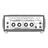
Front Panel Layout:
The front panel is organized for intuitive operation. Key controls include:
- Function Select Switch Bank (1): Allows selection of the desired output waveform (sine, triangle, square, TTL). Only one button should be depressed for correct operation.
- Frequency Range Select Switch Bank (2): Selects the band of output frequencies. The minimum and maximum frequencies for each range are marked. If multiple buttons are pressed, the higher frequency range is selected.
- A.M. Input (3): A BNC socket for external amplitude modulation, allowing modulation of the output from 0% to 100%.
- Sweep Input (4): A BNC socket for wide-band frequency sweeping and narrow-band frequency or phase modulation.
- Frequency Multiplier Control - Coarse (5): A twelve-position switch calibrated as a multiplication factor for the selected frequency range.
- Frequency Multiplier Control - Fine (6): A continuously variable control for fine-tuning the multiplication factor.
- Output Amplitude Control (7): Adjusts the output amplitude from 0 to 30 volts peak-to-peak minimum.
- Output D.C. Offset Control (8): Allows adjustment of the output DC offset from +15V to -15V.
- B.N.C. Socket - TTL Output (9): Provides a TTL-compatible output.
- B.N.C. Socket - 600Ω Output - High (10): Delivers a high-level output from a 600 Ohm source impedance.
- B.N.C. Socket - 600Ω Output - Low (11): Delivers a low-level output (20dB below the high-level output) from a 600 Ohm source impedance.
- On/Off Switch (12): Depresses to apply power to the instrument, providing double pole isolation of the incoming mains supply.
- L.E.D. Indicator On/Off (13): Illuminates when the instrument is on.
Back Panel Layout:
The back panel includes:
- Storage Compartment (14): For storing accessories.
- Container for Fuse and Spare Fuse (15): Holds the main fuse and a spare.
- Mains Input Socket (16): For connecting the mains power lead.
Important Technical Specifications
Frequency Range: 0.1Hz to 500kHz (typically 0.02Hz to >700kHz) in 7 switched decade ranges with fine frequency control.
Frequency Accuracy: 3% of range (typically 1%).
Output Impedance: 600 Ohms (±2%).
Output Amplitude: 0 to 30 Volts p/p min. (low output -20dB).
Output DC Offset: -15 Volts to +15 Volts fully variable.
Output Waveform Purity:
- SINE: Distortion <1.5% (typically 0.5%) up to 100kHz; typically 2% up to 500kHz.
- TRIANGLE: Linearity typically 1% up to 100kHz.
- SQUARE: Mark/space ratio 50% ±1%. Rise and fall times 200ns max. Slew rate 170V/µS typ.
- TTL: Mark/space ratio 50% ±2%. Rise and fall times 25ns max (120pF/225 Ohm load, max load 30 standard TTL inputs).
Output Amplitude Stability: Typically 2% from 0.1Hz to 100kHz.
Frequency Stability: Typically 1% over operating temperature range.
Frequency Setability: Typically better than 0.1%.
External Amplitude Modulation Facility:
- Input Impedance: 6.8kOhms nom.
- Sensitivity: 100% modulation from 6.0 V p/p typical.
- Linearity: Typically 2% up to 95% modulation.
- Maximum Frequency Response: 200kHz (-3dB).
- Maximum Peak Input Voltage: +35V.
External Frequency Sweep Facility:
- Input Impedance: 18k Ohms nom.
- Sensitivity: 0 to 4V for full range sweep up to 120kHz. 0 to 1.7V (typically) for full range sweep on 500kHz range.
- Sweep Linearity: Typically 8% for 1000:1 sweep or 2% for 10:1 sweep within range 0.1Hz to 100kHz.
- Maximum Peak Input Voltage: ±70V.
Mains Input Voltage: 240V, 220V, 110V (set internally) ±10%.
Mains Input Frequency: 48-62Hz.
Environmental Operating Range: 0°C to 40°C (10%-80% RH non-condensing).
Case: Custom-moulded, sturdy, light-weight ABS with tilt stand and rear panel storage compartment.
Size (product only): 219mm x 240mm x 98mm.
Weight (product only): 1.55kg.
Usage Features
Installation:
The Jupiter 500 is set internally for 240V, 220V, or 110V operation, indicated by a label on the back panel.
- Fuse Check: Ensure the fuse in compartment (15) is 100mA for 220V/240V or 200mA for 110V operation.
- Initial Settings: Set Amplitude (7) to min., Offset (8) to centre, Frequency Fine (6) to zero, and Frequency Coarse (5) to 1. Select the 1kHz to 12kHz range on Frequency Range select switchbank (2).
- Power On: Connect the mains lead to socket (16), depress On/Off Switch (12), and confirm L.E.D. (13) illuminates.
- TTL Output Test: Connect TTL Output (9) to an oscilloscope or frequency counter and confirm a 1kHz output.
- Amplitude Test: Rotate Amplitude (7) a quarter turn clockwise. Confirm output with Sine, Triangle, and Square selected, using both High and Low Outputs (10, 11).
- DC Offset Test: Confirm DC Offset Control (8) produces a DC shift using High Level Output (10) with an oscilloscope or Low Level Output (11) for a frequency counter.
Controls Operation:
- Power Switch (12): Provides double pole isolation.
- Function Select (1): Selects output waveform. Only one button should be active.
- Range Select (2): Selects frequency band. Higher range is selected if multiple buttons are active.
- Frequency Multiplier - Coarse (5): A 12-position switch for setting the multiplication factor. For optimum performance, select the lowest possible range and a high multiplier figure.
- Frequency Multiplier - Fine (6): Continuously variable for fine-tuning the frequency. Calibration is achieved when set to -1. This control allows operation below the design minimum frequency for a given range, though with potential increases in distortion, jitter, and non-linearity.
- Amplitude (7): Varies output amplitude. Some amplitude loss may occur above 100kHz, especially for sine waves.
- D.C. Offset (8): Adjusts output DC offset. Clipping may occur if maximum offset and amplitude are set simultaneously.
Inputs:
- A.M. Input (3): Allows modulation of the output from 0% to 100%. For conventional AM, the DC level of the AM Input must be biased to the 50% level, with the modulating signal superimposed.
- Sweep Input (4): Enables wide-band frequency sweeping. The input voltage/frequency sweep ratio depends on the selected range. The maximum useful sweep range is -6V to +6V, with protection up to ±70V.
Outputs:
All outputs are short-circuit protected but offer only partial protection against external voltages.
- TTL Output (9): Short-circuit proof, drives up to 30 standard TTL loads. It is of opposite sense to the square wave output and leads sine/triangle waves by 90 degrees and square waves by 180 degrees.
- High Level 600 Ohm Output (10): Delivers 30V peak-to-peak from 600 Ohms source impedance with up to ±15V DC offset. It can drive impedances down to 600 Ohms.
- Low Level 600 Ohm Output (11): Delivers the same output as the high-level output but at -20dB (1/10th) of the level. It is unaffected by low impedance loads unless the high-level output is overloaded.
Use of Cables & Probes:
All BNC sockets are 50 Ohm types. For the TTL Output, keep leads short to avoid capacitive loading and transmission line effects. For the Sweep Input, use low source impedance, short screened cables, and keep away from noise sources to avoid frequency jitter.
Applications:
- Audio Testing: Uses square waves to detect amplifier frequency response anomalies, crossover distortion, instability, and phase shift. Triangular waves can also demonstrate crossover distortion.
- Cassette Recorder Testing: Recording and playing back square waves can reveal distortion types common in cassette recorders, particularly phase shift.
- Frequency Response Testing: Requires an oscilloscope with XY input or external timebase. A sawtooth or triangle waveform from a second Jupiter 500 can drive the oscilloscope's X input, while the Jupiter 500's sine wave output feeds the amplifier input and the amplifier's output goes to the oscilloscope's Y input.
- I.F. Alignment: Possible on radios with I.F. frequencies of 500kHz or less (e.g., 455kHz). Two methods:
- By Ear: Drive the AM Input with an amplified signal, set output to I.F. frequency sine waves, connect Low Output to I.F. strip input, and trim ferrite dust cores for maximum volume and clarity.
- With Equipment: Set up for frequency response testing, driving the Jupiter's Low Output into the I.F. strip input. Take the output from the detector to the oscilloscope. Trim ferrite cores for maximum amplitude and flatness over the trace.
- Chart Recorder Testing: The Jupiter 500's very low frequency operation allows easy checking of recorder plot accuracy, linearity, and speed. Its high output voltage can drive most chart recorders directly.
- Loudspeaker Testing: Used with a calibrated microphone and audio voltmeter, the Jupiter 500 can directly drive power amplifiers for checking loudspeaker response in different room environments.
Maintenance Features
Safety and Protection:
- Do not open the case without totally disconnecting the unit from mains.
- The high-level output can reach up to 30V, so caution is advised when using it, especially with unprotected circuits.
- The instrument must be earthed.
Power Requirements:
- Operates from 50 or 60Hz supply (240V, 220V, or 110V) with ±10% tolerance.
- Replacement Fuse Values:
- 240V and 220V operation: 20mm anti-surge fuse 100mA.
- 110V operation: 20mm anti-surge fuse 200mA.
- A spare fuse can be carried in the fuse holder. Fast-blow fuses must NOT be used.
Maintenance and Repair:
- The manufacturer or appointed agent will repair and calibrate faulty instruments. Refer to the guarantee card for details.
- When returning for repair:
- Do NOT return accessories.
- Pack carefully, preferably in original packing.
- Enclose a covering letter with full fault information.
- Enclose proof of purchase.
- Owners undertaking their own repairs and calibration should be skilled personnel with access to precision equipment and the Service Manual.
- Cleaning: Clean the outside with a damp (NOT WET) cloth and a little detergent. Stubborn marks can be removed with alcohol-based solvents (methylated spirit or iso-propyl alcohol); do not use commercial or industrial solvents.
- Controls: Pre-lubricated for life under normal conditions; switch cleaner/lubricant should not be needed until out of guarantee.
- Environmental Considerations: High temperatures, dusty/gritty surroundings, or high vibration environments can reduce instrument life and affect the guarantee. Storage or use in damp, wet, or humid surroundings is prohibited. It is recommended not to use the instrument outdoors unless a suitable earth leakage protection device is in circuit.
Calibration:
Calibration is a complex procedure requiring specialized equipment and experienced electronic technicians. A service manual with full details is available.
Guarantee:
Refer to the separate guarantee card inserted in the manual for details.