Page 2Rev. 120814
Part Description Qty
1 Stop plate 1
2 Bolt M10x20 10
3 Bolt M10x25 2
4 Adjustable shelf 1
5 Bolt M8x12 4
6 Movable vice assy 1
7 Stationary vice assy 1
8 Platform 1
9 Removable plate 1
10 Ramp 1
11 Detent bar 1
12 Clevis pin 2
13 R-pin 4
14 Handle socket 1
15 Bolt M16x100 2
16 Washer 016 4
17 Lock nut M16 2
18 Lifting arm 1
19 Bolt M16x70 2
Part Description Qty
20 Lock washer 016 2
21 Nut M16 2
22 Retaining ring 6
23
Frame/cylinder pivot shaft
1
24 Lifting arm 1
25 Cylinder end plate 1
26 Lock nut M10 2
27 Nut M10 20
28 Lock washer 010 6
29 Washer 010 20
30 Stay bolt 4
31 Cylinder 1
32 Nut M20 1
33 Piston 1
34 O-Ring 1
35 O-Ring 1
36 Seal ring 1
37 Press ring 1
38 Retaining ring 1
Part Description Qty
39 Piston rod 1
40 O-Ring 2
41 Shaft bushing 1
42 Dust proof ring 1
43 O-Ring 1
44 O-Ring 1
45 Front cover 1
46 Nut 1
47 Air hose 1
48
Foot-operated air valve
1
49 Air hose connector 1
50 Washer 012 2
51 Wheel 2
52 Connection 1
53 Bolt M10x45 2
54 Cam roller bearing 4
55 Washer 4
56 Cam bearing spacer 2
57 Roller 2
Specications
• Capacity: 1000 lbs (454 kg)
• Length: 78-3/4” (2000mm)
• Max Height: 32-9/32” (820mm)
• Air Inlet Fitting: 1/4” NPT
• Width: 24” (610mm)
• Min Height: 7-1/16” (180mm)
• Air Pressure: 90-100PSI
Assembly
Parts List
Use the exploded drawing as your guide to assemble. Lay all parts and assemblies out in front of you
before beginning. The following procedure is recommended. Should there be any damaged or miss-
ing parts, contact your supplier immediately.
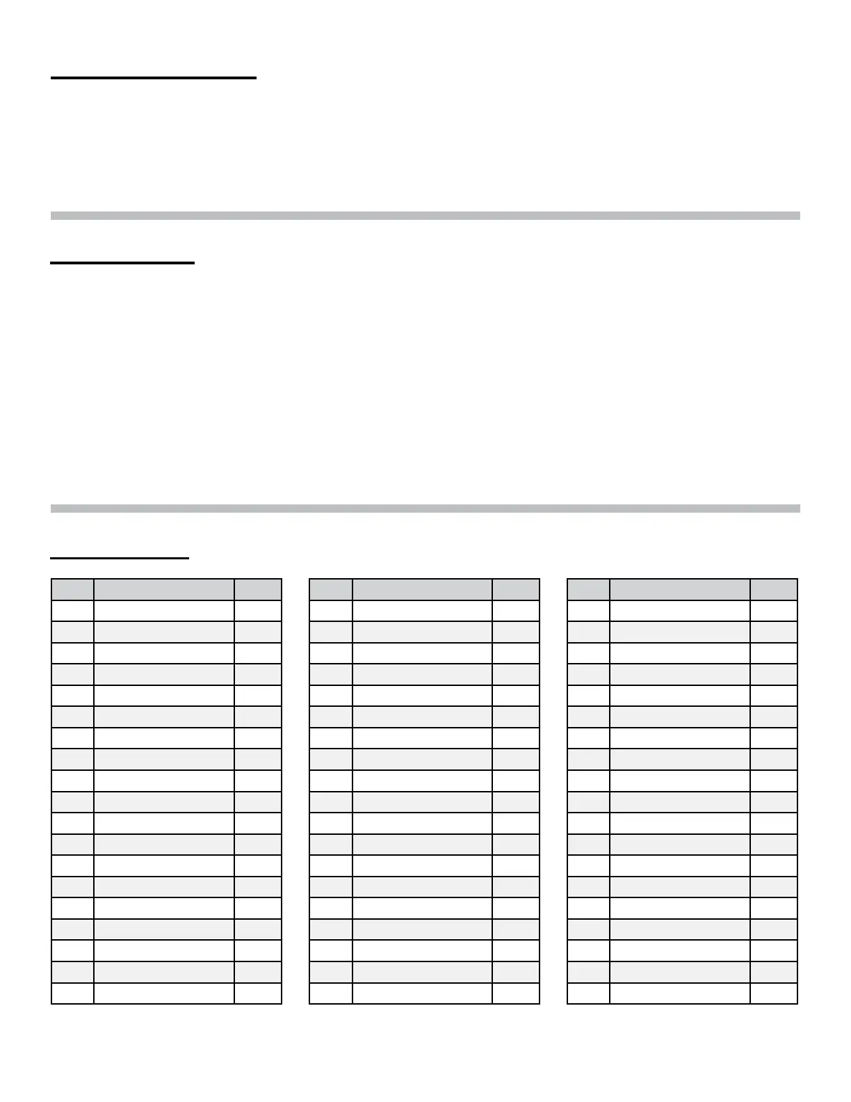
1. Attach the ramp (10) to the end of the platform.
2. Place the removable plate (9) to the platform (8) to cover the rear wheel removal aperture.
3. Assemble the stop plate (1) and wheel vise assemblies (6, 7) to the front of the platform using bolts
(2), washers (29), and nuts (27).
4. Connect foot-operated air valve (48) to a maximum 100psi air supply.


 To Next Page