ENGLISH
4
COMPONENTS FIG. A
WARNING: Never modify the power tool or any part
of it. Damage or personal injury couldresult.
Refer to Figure A at the beginning of this manual for a
complete list ofcomponents.
INTENDED USE
This appliance is designed for household outdoor
blowerapplications.
DO NOT use under wet conditions or in presence of
flammable liquids orgases.
DO NOT let children come into contact with the tool.
Supervision is required when inexperienced operators use
thistool.
ASSEMBLY AND ADJUSTMENTS
WARNING: To reduce the risk of serious personal
injury, turn unit off and unplug before making
any adjustments or removing/installing
attachments or accessories. An accidental start-up
can causeinjury.
Blow Tube Assembly (Fig. C, D)
• To attach the blower tube
3
to the power head, line up
the peg
6
on the bottom of the power head with the
notch
7
on the bottom of the blower tube opening as
shown in fig. C.
• Push the blower tube onto the power head until the
tube locks
2
engage the blower tube and an audible
click is heard.
• Pull on the tube to ensure it is securely in place.
• To remove the tube, press in and the two tube locks
2
and pull tube off as shown in fig. D.
Fig. C
7
3
6
Fig. D
2
2
OPERATION
WARNING: Do not operate blower without blow
tube securely in place. Never reach down into housing
through tubehole.
WARNING: Always wear safety glasses. Wear a filter
mask if the operation is dusty. Use of rubber gloves
and substantial footwear is recommended when
working outdoors. For household useonly.
WARNING: Cut Hazard. When turning the tool
off, wait 10 seconds for the fan to stop rotating
beforeremoving the blower tube.
• Always switch off and remove the plug from the
electrical supply when:
- The power supply cord has become damaged
orentangled.
- You leave blowerunattended.
- Clearing ablockage.
- Checking, adjusting, cleaning or working on blower.
• Use blower only in daylight or good artificiallight.
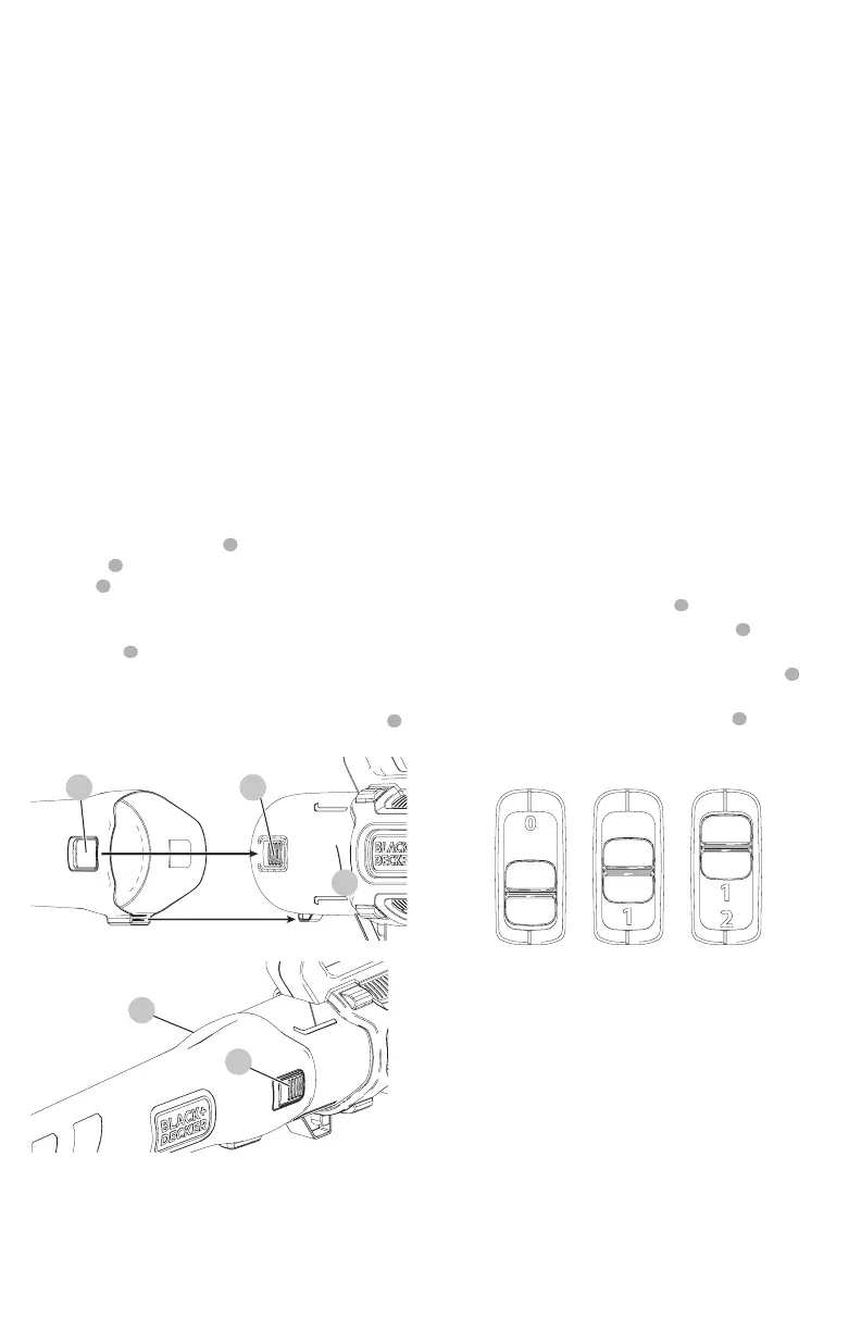
Switching ON/OFF (Fig. E)
WARNING: Use both hands to grip the product firmly
when switchingon.
CAUTION: Do not point unit discharge at self
orbystanders.
WARNING: Cut Hazard. When turning the tool
off, wait 10 seconds for the fan to stop rotating
beforeremoving the blower tube.
Your blower is fitted with a 2 speed ON/OFF switch located
on the top of the power head handle
5
.
• To switch the blower ON, slide the ON/OFF
1
switch
forward to position 1 as shown in Fig.L.
• To operate blower in high speed, slide the ON/OFF
1
switch forward to position 2 as shown in Fig.L.
• To switch the blower off, slide the ON/OFF
1
switch
back as shown in Fig.E.
Fig. E
Cord Retainer (Fig. F)
• A cord retainer is incorporated into the rear of the
power head. It can be used in two different ways:
• To use the cord retainer as shown in Fig. F, make a loop
with the extension cord. Slide the extension cord loop
through the back of the power head and hook the
extension cord under the retainer. Then plug the cord
from the power head into the extensioncord.
• To use the cord retainer as shown in Fig. F, make a
loop with the extension cord. Slide the extension cord
loop through the back of the power head and hook
the extension cord under the retainer. Then loop the
extension cord over the power head cord and plug the
two ends into each other.