Do you have a question about the Blackstar DEPT. 10 DUAL DRIVE and is the answer not in the manual?
Explanation of warning symbols indicating important operation and potential electric shock risks.
Connect your guitar to the input jack using a screened guitar lead.
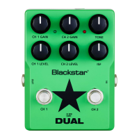
Adjusts overdrive/distortion for Channel 1, increasing gain for more overdriven tones.
Sets overall volume for Channel 1, used with Gain 1 for desired drive and volume.
Switches Channel 1 between Clean and Crunch modes, offering versatile tone options.
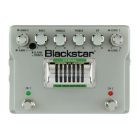
Adjusts low-end frequencies for tight, cutting, or warm, thumping tones.
Adjusts mid-frequencies for tone 'body', from scooped rhythm to sustained lead tones.
Fine-tunes treble frequencies for warm, dark, or bright, cutting sounds.
Infinite Shape Feature adjusts tone signature between American and British characteristics.
Adjusts overdrive/distortion for Channel 2, from crunch to screaming lead tones.
Sets overall volume for Channel 2, used with Gain 2 for desired drive and volume.
Selects one of three Cab Rig speaker environments for detailed sound shaping.
View of ECC83 valve; warning against removing guard as there are no user serviceable parts.
Sets Channel 2 between Crunch (dynamic) and Overdrive (higher gain, presence).
Connects to other pedals or amp inputs; recommended first in effects chain for tone preservation.
DSP speaker simulator output for cabinet detail, edit via Architect software.
Indicates if Channel 1 is active (WHITE LED on) or inactive (LED off).
Toggle Channel 1 on or off with this footswitch.
Indicates if Channel 2 is active (RED LED on) or inactive (LED off).
Toggle Channel 2 on or off with this footswitch.
Connects the input of an external effects unit to keep signal clean.
Connects the output of an external effects unit.
Input for the 9V DC / 500mA power adaptor. Only use the included supply.
Connects to PC/Mac for audio capture, with Cab Rig preset applied or DI signal.
Balanced output for PA, mixing desk or interface, with Cab Rig preset or DI signal.
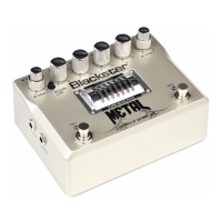
The Blackstar DEPT. 10 DUAL DRIVE is a high-voltage valve effects pedal designed to offer extensive overdrive flexibility for guitarists. It is the result of meticulous research and development by Blackstar's R&D team, DEPT. 10, based in Northampton, UK. The pedal aims to provide guitarists with ultimate tools for self-expression, ensuring reliability, quality, and superior tone through extensive laboratory and road testing.
The DEPT. 10 DUAL DRIVE pedal features two channels, each offering distinct drive characteristics. Channel 1 provides Clean and Crunch modes, allowing users to transition from a clean boost to a full overdrive. Channel 2 extends the tonal range, moving from a super crunch to a screaming lead. At its core, the pedal utilizes an ECC83 valve, visible through a protective guard, to deliver authentic valve tone.
A key feature of this pedal is its unique switching operation, which can transform a single-channel vintage amplifier into a three-channel tone machine. This expands the versatility of a guitarist's setup without needing multiple pedals or a complex rig.
The pedal also incorporates Blackstar's patented ISF (Infinite Shape Feature) control. This allows for continuous adjustment of the tone signature, effectively blending characteristics from American-style amplifiers (tight bottom end, aggressive mids) to British-style amplifiers (woody, less aggressive). This feature works in conjunction with the traditional Bass, Middle, and Treble controls, providing comprehensive tonal sculpting.
For recording and direct connection, the DEPT. 10 DUAL DRIVE includes a Cab Rig output. This is a next-generation DSP speaker simulator that meticulously reproduces the sound and feel of a mic'd guitar cabinet. Users can select from three Cab Rig environments directly on the pedal or delve into deep editing and create custom patches using the free Architect software via USB. The Cab Rig output is a stereo 6.35mm connection, suitable for headphones, studio monitors, and front-of-house systems, and features a low-noise, low-distortion headphone driver circuit for silent practice. Additionally, an XLR Line/DI Output provides a balanced connection for PA systems, mixing desks, or recording interfaces, also benefiting from the selected Cab Rig preset. A DI signal can be chosen within the Cab Rig software to bypass cabinet simulation for both the USB and XLR outputs.
The pedal's top view features several controls for intuitive operation:
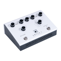
The rear view of the pedal offers additional connectivity:
The manual emphasizes several important safety and maintenance instructions to ensure the longevity and safe operation of the DEPT. 10 DUAL DRIVE pedal:
The pedal is designed for safe use under non-tropical climate conditions, with a maximum ambient temperature of 35°C, and evaluated for safety at a maximum altitude of 2000m.
| Technology | Analog |
|---|---|
| Tubes | No |
| Channels | 2 |
| MIDI | No |
| USB | No |
| Weight | 0.5 kg |
| Type | Overdrive |
| Switches | Bypass |
| Inputs | 1 x 1/4" Instrument Input |
| Outputs | 1 x 1/4" Output |
| Power Supply | 9V DC (Power Supply Included) |