www.blaubergventilatoren.de
S30, S31, S32
11
Position Description
1 Digital inputs
2 Analogue inputs
3 Analogue outputs
4 Digital outputs
5 Micro USB for updating applications, import and export of
settings, alarm log
6 Power source for external sensors
7 Ethernet port
8 Connection port for PGDe control panel
9 Display port
10 BMS/Fieldbus2 port
11 BMS/Fieldbus1 port. Used for connection of th-Tune as well
12 Slot for connection of BMS card (not included in the delivery
set, available as a specially ordered accessory)
13 Jumpers for configuration of BMS/Fieldbus2 port
14 Power input
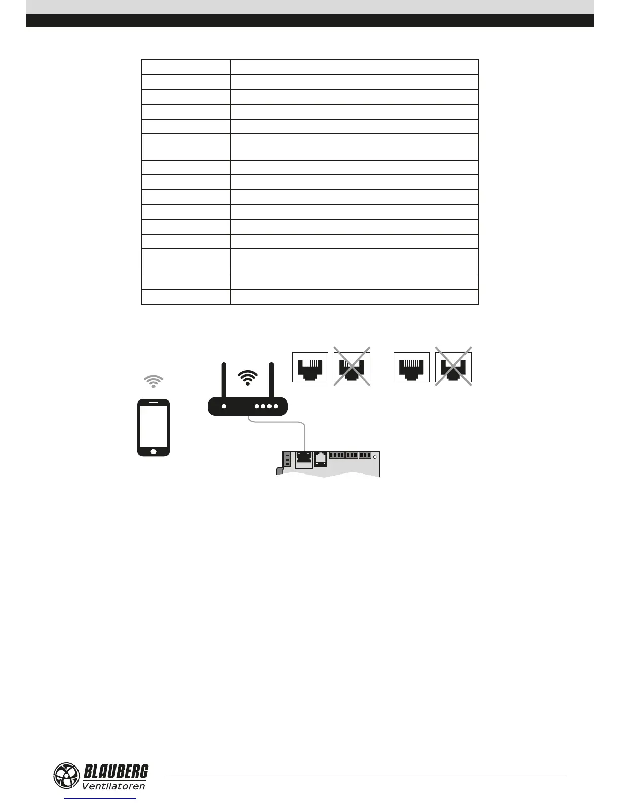
Ventilation unit control with a mobile device
Ethernet Internet
LAN WAN
The ventilation unit is controllable via a mobile device or tablet. Connect the router through the Ethernet (LAN) connector using the
twisted pair (4 x 2 x 0.51) not below Cat5 with 8P8C connectors. Go to router menu and find IP address of the ventilation unit. Enter IP
address in the URL bar in a mobile device.
After that the unit is ready for operation via mobile device. The control interface is identical to the PGDe control panel interface.