S30, S31, S32
8
www.blaubergventilatoren.de
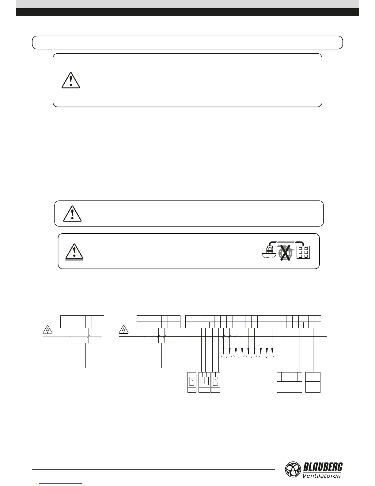
CONNECTION TO POWER MAINS
DISCONNECT THE UNIT FROM POWER MAINS PRIOR TO ANY OPERATIONS.
THE UNIT MUST BE CONNECTED TO POWER SUPPLY BY A QUALIFIED ELECTRICIAN.
THE RATED ELECTRICAL PARAMETERS OF THE UNIT ARE GIVEN ON THE
MANUFACTURER’S LABEL.
• The unit is rated for connection to single-phase 230 V/50 Hz or three-phase 400 V/50 Hz power mains (refer to Technical data) in
compliance with wiring diagrams.
• The unit must be connected to power mains using durable, insulated and heat-resistant conductors (cables and wires). The actual wire
cross section selection must be based on the maximum load current, maximum conductor temperature depending in the wire type,
insulation, length and installation method.
• The external power input must be equipped with an automatic circuit breaker QF built into the stationary wiring to open the circuit in
the event of overload or short-circuit. The position of the external automatic circuit breaker must ensure free access for quick power-
off of the unit. The trip current of the automatic circuit breaker must exceed the maximum current consumption of the unit (refer to
the “Technical data” section). The recommended trip current of the circuit breaker is the next current in the standard trip current row
following the maximum current of the connected unit. The automatic circuit breaker is not included in the delivery set and can be
ordered separately.
DO NOT LAY THE VENTILATION UNIT POWER CABLE IN CLOSE
PROXIMITY TO THE CONTROL PANEL CABLE!
DO NOT COIL THE CABLE FROM THE CONTROL PANEL IN LOOPS WHILE
LAYING IT.
Route the cables to the control unit via the cable glands on the air handling unit.
Complete the electric connections in compliance with external wiring diagram via the terminal blocks in the control unit.
L3 N1L L1 L2 N
X1 X2
PE
 Loading...