This document serves as a comprehensive service manual for the Blaupunkt Renault G5 RDS car radio, including the Clio variant. It provides detailed instructions for electrical alignment, disassembly, and testing, catering to service technicians.
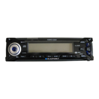
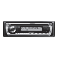
The primary function of the device is a car radio with RDS (Radio Data System) capabilities, designed for Renault G5 and Clio vehicles. It supports FM, AM/MW (Medium Wave), and LW (Long Wave) bands, and includes a cassette tape drive. The RDS functionality allows for the reception of traffic information messages (ARI) and other data broadcast by FM stations.
Technical Specifications (derived from alignment procedures):
- Power Supply: 12 V, adjustable, 10 A (for service).
- Loudspeaker Output: 4 Ω termination required for alignment.
- FM Frequencies: Alignment procedures specify 98.2 MHz.
- AM Frequencies: Alignment procedures specify 810 kHz (MW) and 252 kHz (LW).
- Signal Generator Levels (for alignment):
- FM: E' = 30 dBμV (unloaded antenna input), Y = 36 dBμV (with dummy antenna).
- AM: E' = 30 dBμV (unloaded antenna input), Y = 50 dBμV (with dummy antenna).
- FM Deviation (for alignment): 22.5 kHz and 75 kHz.
- Modulation Frequency (for alignment): 1 kHz.
- IF Programming: Stores the valid intermediate frequency in the RPL processor.
- Phase Shifter Alignment (FM): Adjusts F152 to achieve 5V at MP-SL and an A.C. minimum at MP-AM.
- IF Limits Adjustment: Sets the FM IF limits to achieve a 10 dB ± 2 dB volume drop when the signal is reduced by 52 dBμV.
- Search Tuning Sensitivity (Lo/Dx): Programmable for both FM and AM bands, with different signal levels (e.g., FM Lo at 46 dBμV, FM Dx at 25 dBμV; AM Lo at 40 dBμV, AM Dx at 20 dBμV).
- RDS Basic Sensitivity: Programmable at 30 dBμV for FM.
- ARI Volume Level: Programmable to adjust the basic volume for traffic information messages, typically set to achieve 50 mV ± 5 mV output.
- Telephone Mute: Tests for a signal level drop greater than 50 dB when pin 4 of block III is connected to ground.
- Viewing Angle Adjustment: Allows for adjustment of the display viewing angle (Angle -1, 0, +1) in a special "Disturbed Mode."
Usage Features (from a service perspective):
- Station Presets: The device utilizes station buttons that need to be programmed with specific frequencies for alignment purposes (e.g., 810 kHz for AM/MW, 252 kHz for AM/LW, 98.2 MHz for FM).
- Audio Settings: Treble/bass settings are set to a medium position for alignment.
- Display: The display provides feedback during programming and alignment, such as "ZF Prog" and flashing numbers (1, 2, 3, 4, 5) to confirm successful programming steps.
- Manual Tuning: The manual tuning switch is set to 12.5 kHz steps during IF programming.
- Rocker Switch (<<, >>): Used for adjusting A.C. minimum during IF programming.
- Volume Control: Used to adjust output voltage during IF limits adjustment and ARI volume programming.
- Special Modes:
- Disturbed Mode: A special function for Renault car radios, activated by pressing buttons 2 and 3 simultaneously while turning the radio on. In this mode, all radio functions are operable, a beep sounds every two seconds, the radio mutes after two minutes displaying "CODE," and it plays for two minutes after being switched off and on. This mode is deactivated upon entering the code number.
- Viewing Angle Adjustment Mode: Accessed via the Disturbed Mode, allowing adjustment of the display's viewing angle using AF, TS, and TA buttons. Default settings are Angle 0 for Renault G5 and Angle -1 for Renault G5 Clio.
Maintenance Features (for service technicians):
- Electrical Alignment: Requires specific equipment including a power supply, signal generator, high-resistance voltmeter, output meter, oscilloscope, probes, frequency counter, ceramic adjusting pins, and a soldering iron.
- Shielding: RF alignment must be performed with the bottom cover in place. Wires should be soldered to measuring points and routed outside the unit.
- Component Replacement: If frequency-determining components are replaced or adjusted, AM and FM alignment must be performed. However, if the FM module (8 638 302 645) or AM module (8 638 302 981) are replaced, no tuner-specific alignments are necessary as these modules are pre-aligned.
- RDS Processor Replacement: After replacing the RDS processor V2400, all unit parameters must be reprogrammed.
- Dummy Antenna (8 627 105 356): Essential for alignment, with specific voltage requirements for AM (0V) and FM (+12V) measurements.
- Disassembly: Detailed steps are provided for removing the front panel and cassette tape drive, including unscrewing various components (screws A, D, H), removing clamps (B), and carefully disconnecting cables (G, P1350, N1303). Technicians are advised to note cable positions during disassembly.
- Measuring Points: Specific measuring points (MP-PROG, MP-RPL, MP-AM, MP-SL) are identified on the main board for various alignment procedures.
- Solder Side Access: Measuring points on the solder side should be routed outwards for easier access during alignment.
- dB Conversion Table: Provided to assist with signal level calculations during alignment.
The manual also includes detailed circuit board layouts (Hauptplatte, AM-Platte, FM-Platte, Schalterplatte, Zusatzplatte) with component identifiers and pin descriptions for various connectors (DV600, DV2000, DV2001/II, DX1, N1300, N1303, N1350, P850, P851, P852, N850, N851, N852, P2801). These layouts are crucial for identifying components and test points during service and repair.