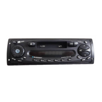
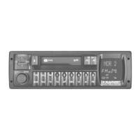
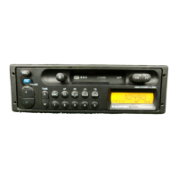
This document describes the Blaupunkt Düsseldorf RCR 84 and Windsor RCR 84 car radios, providing detailed information on their functions, technical specifications, usage, and maintenance.
The devices are car radios featuring an AUTORADIO function with RDS-Plus Tuner with EON (Enhanced Other Network), TP (Traffic Program), TA (Traffic Announcement), DSC (Direct Software Control), and Codem III (Coincidence demodulator Type III). They offer both FM and AM radio reception, with a cassette player for audio playback.
Function Description:
The core function of these devices is to provide radio reception and cassette playback in a vehicle.
- Radio Data System (RDS): This feature allows the radio to receive additional digital information broadcast by FM radio stations.
- EON (Enhanced Other Network): Enables the radio to monitor other networks for traffic announcements or other program types, even when not tuned to that specific station.
- TP (Traffic Program): Indicates that the tuned station broadcasts traffic information.
- TA (Traffic Announcement): Automatically switches to a traffic announcement when one is broadcast, even if the user is listening to a cassette or another radio station.
- DSC (Direct Software Control): Likely refers to a feature that allows for software-controlled adjustments or enhancements to the radio's performance, possibly related to signal processing or user interface.
- Codem III (Coincidence demodulator Type III): This is a type of demodulator used in radio receivers, likely contributing to improved signal reception and quality, especially in challenging reception conditions.
- FM-Modul (8 638 302 645) and AM-Modul (8 638 302 981): These modules are integral to the radio's tuner section, responsible for processing FM and AM signals, respectively. They are factory-aligned, meaning that specific tuner alignment procedures are not required if these modules are replaced.
- Cassette Section: The integrated cassette player features Autoreverse with Tracking Logic and Pinch Roller Release, and Dolby B noise reduction, enhancing the audio quality of cassette playback.
- Amplifier Section: The devices include a Double Bridged Amplifier with integrated Flex-Fader, providing audio output to four loudspeakers.
Important Technical Specifications:
General:
- On-board power supply: 12 V
- Test voltage: 14.4 V
- Operating voltage range: 10.8 V - 15.6 V
- Current drain (I - min): 2 mA
- Current drain (I - max): 0.7 A
- Current drain (I - max): 9 A (likely maximum operating current)
Radio Section FM (RDS-Plus Tuner with EON):
- Frequency: 87.5 - 108 MHz
- Presets: 4 x 6 FM (24 programmable stations)
- Tuning steps: 100 kHz with automatic tuning, 50 kHz with manual tuning
- Sensitivity: 0.9 µV / 26 dB S/N
- Limiting Threshold: 7 µV for -3 dB
- Seek tuning sensitivity (FM - dx): 20 dBμV
- Seek tuning sensitivity (FM - lo): 40 dBμV
- Selectivity: > 80 dB at ± 300 kHz, > 40 dB at ± 200 kHz
- Crosstalk attenuation: > 30 dB at 1 kHz
- Frequency response: 35 - 15 000 Hz (-3 dB)
- Multi - ARI Traffic programmes: TP, TA, SK, DK
Radio Section AM (Windsor RCR 84 specific, but likely similar for Düsseldorf RCR 84):
- MW (Medium Wave): 531 - 1602 kHz
- LW (Long Wave): 153 - 279 kHz
- Presets: MW 1 x 6, LW 1 x 6 (12 programmable stations)
- Tuning steps: MW 9 kHz / 9 kHz, LW 9 kHz / 1 kHz
- Seek tuning sensitivity (AM - dx): 17 dBμV
- Seek tuning sensitivity (AM - lo): 35 dBμV
Amplifier Section:
- Output power (Sinus): 4 x 19 W / 2 x 24 W (according to DIN 45324/3.1)
- Output power (Music): 4 x 20 W / 2 x 25 W (according to DIN 45324/3.2)
- Distortion factor: 10% at 4x19 / 2x24 W Sinus
- Frequency response: 25 - 20 000 Hz (-3 dB)
- Sound control range: Treble ±12 dB at 10 kHz, Bass ±12 dB at 100 Hz
- Signal-to-noise ratio: > 60 dB
- Channel separation: 50 dB (1 kHz)
Cassette Section:
- Tape speed: 4.75 cm / sec.
- Reel time (C60): 120 sec.
- Drift: ±2%
- Flutter: 0.25%
- S/N - Ratio: 64 dB with Dolby B, 56 dB without Dolby B
- Cross-talk attenuation: > 60 dB
- Frequency response: 35 - 16 000 Hz (-3 dB)
Usage Features:
The manual provides clear operating hints for basic functions:
- Switching the radio on: Turn the on/off knob (1).
- Choosing the frequency range: Press button (3) for FM 1 (domestic) or FM 1-T (foreign countries).
- Setting the frequency manually: Use the search tuning rocker switch (2) (labeled "<<" and ">>") to adjust the desired frequency. FM frequencies are spaced in 50 kHz steps, MW in 9 kHz steps, and LW in 1 kHz steps (export version). A brief press changes frequency in single steps, while holding it down changes it rapidly. It's important to note that FM 50 kHz steps are not displayed, so users must ensure correct channel frequencies.
- Storing the frequency: Hold down the station button (4) for at least 2 seconds until the radio mutes and a beep sounds. The display will then show the number of the stored station button.
Maintenance Features:
The manual outlines several electrical alignment procedures and important mechanical notes:
- Electrical Alignment: This is divided into IF programming, FM alignment and programmings, and AM alignment and programmings (for foreign countries).
- Notes on alignment: Alignment is necessary if frequency-determining components are replaced or adjusted. However, the FM and AM modules (8 638 302 645 and 8 638 302 981) are factory-aligned, so no tuner-specific alignments are needed if these modules are exchanged.
- RDS processor: If the RDS processor V2400 is replaced, all unit parameters must be reprogrammed.
- Signal generator level values: Specific signal generator levels are provided for alignment, with adjustments for dummy antenna losses.
- Dummy antenna (8 627 105 356): Instructions for connecting the dummy antenna for AM (0 volts) and FM (+12 volts) measurements.
- Radio-shielding: RF alignment must be performed with the bottom cover in place. Wires should be soldered to measuring points and routed outside the unit.
- Required equipment: A list of necessary equipment for alignment is provided, including a power supply, signal generator, voltmeter, output meter, oscilloscope, probes, frequency counter, screwdrivers/adjusting pins, and a soldering iron.
- Preparation work: Before electrical alignment, the treble/bass settings should be set to the medium position, and specific frequencies must be programmed to the station buttons.
- Loudspeaker connections: The loudspeaker output must be terminated with 4 Ω.
- Mechanical Notes: After replacing the audio head, the fixing screws must be secured with varnish. Detailed disassembly steps are provided for the facia, potentiometer knob, and cassette tape drive, including instructions for removing screws, pulling off components, unsoldering, and unhooking.
The document includes detailed circuit diagrams and exploded views for various boards (AM board PL02, Key board PL42, FM board PL06, Main board PL20, Connector board PL74) and the cassette drive (Mini-18 LW 1300), along with comprehensive spare parts lists for both electrical and mechanical components.