EasyManua.ls Logo

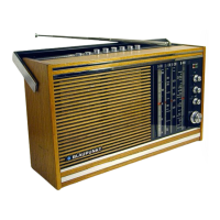
Blaupunkt KOFFERRADIO Marimba - Alignment Table and Points; Alignment Table Details; Alignment Point Locations

Blaupunkt KOFFERRADIO Marimba
15 pages
To Next Page IconTo Next Page
To Previous Page IconTo Previous Page
Loading...
Abgleichtabelle
Wellenbereiche:
87,4
108
MHz
5,98—
6,25
MHz
515
1640
kHz
18
255
kHz
UKW
Kw
MW
LW
3,43
2,78m
50,20—
48
m
584
182
m
1176
—2040
m
Bereich
MeBsender
Skalenzeiger
Waveband
Sign.
Gen.
Pointer
über
Spannungsteiler
Fig.
2
Alignment
Table
Wavebands:
87.4
108
MHz
5.98
`
6.25
MHz
5155
1640
kHz
148
255
kHz
3.43
2.78
50.20
48
584
182
1176
2040
UKW
Kw
MW
m
m
m
LW
m
HF
Empfindlichkeit
bezogen
bei
AM
auf
50
mW
Ausgangsistg.;
FM
auf
0,5
V
Ratiospannung
RF
sensitivity
on
AM
for
50
mW
output;
FM
for
0.5
V
ratio
voltage
Abgleichelemente
Trimming
points
ab
Basis/from
base
V
101
(3)
über
Spannungsteiler/via
voltage
divider
20:1
0,46
3)
(0,452)
via
voltage
divider
Fig.
2
1600
M
(ZF
/
IF)
ab
from
(3)
L
51,
L
41,
L
35,
L
26,
L
21
auf
Maximum
/
to
maximum
ca./approx.
400
uV
bei
M
und
L
im
homogenen
Feld
on
M
and
L
in
homogeneous
field
Vorkreis
Pre.
circ.
Oszillator
Oscillator
ca./approx.
60
uV/m
ca./approx.
25
uV/m
über
1
nF
an
(4)
via
1
nF
to
(4)
über
60
Q
Kabel
via
60
2
cable
Zwischenkreis
ca./approx.
200
uV/m
ca./approx.
90
uV/m
ca./approx.
4uV
über
Spannungsteiler/via
voltage
divider
10:1
L
57,
L
55,
L
46,
L
45,
L
32,
L31,
L
15,
L
73
auf
max.
Ratiospannung
to
max.
ratio
voltage
')
R
131
auf
to/Min.
Outputmeter|
ab
Basis/from
base
V
102
L
15
verstimmen/detune
L
15
ca./approx.
400
“V
ab
Antennenanschluß
Oszillator
f
Int.
circ.
Oscillator
from
antenna
connection
Antenne/antenna
1)
Ein
AM-Signal,
400
Hz,
30°/o
moduliert,
soll
eine
Ratio-
spannung
von
1,0
V
erzeugen.
Dann
mit
R
131 ein
Span-
nungsminimum
am
Outputmeter
einstellen,
Fig.
5.
2)
Koppelspule,
ca.
20
Windungen,
6
cm
Durchmesser,
an
das
MeBsenderkabel
anschließen
und
in
die
Nähe
des
Ferritstabes
bringen.
Abgleich
nach
der
Abgleichtabelle.
3)
Bei
Geräten
mit
besonderer
Kennzeichnung
AM
ZF
452
kHz
=
0,452
MHz.
ca./approx.
2
uV
|
1)
An
AM
signal,
400
Hz,
30%
modulated,
must
produce
a
ratio
voltage
of
1.0
V.
Adjust
a
voltage
minimum
at
the
outputmeter
by
means
of
R
131,
see
fig.
5.
2)
Connect
coupling
coil,
approx.
20
wdgs.,
2.36”
(h
to
cable
of
signal
generator
and
approach
the
coil
to
ferrite
an-
tenna.
Align
according
to
alignment
table.
3)
For
sets
with
special
indication
IF
AM
452
kHz
=
0,452
MHz.
Lage
der
Abgleichpunkte
/
Position
of
Alignment
Points
ENG
e
o
c87
L72
om)
R131
L57
[K1091]
Silt
oe

Related product manuals