EasyManuals Logo

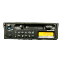
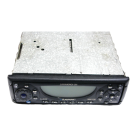
Blaupunkt Sao Paulo RCR 27 Service Manual

Blaupunkt Sao Paulo RCR 27
34 pages
To Next Page IconTo Next Page
To Previous Page IconTo Previous Page
Page #8 background imageLoading...
Page #8 background image
(®)
FM-Abgleich
Bitte
achten
Sie
darauf,
da8
die
Stationstasten
vor
dem
Abgleich
mit
bestimmten
Frequenzen
belegt
werden
missen
(siehe
Seite
4)
Einstellung
der
ZF
-
Begrenzung
Kanstliche
Antenne
(8
627 105
356)
verwenden.
Betriebsart
.FM
Stationstaste
.
4
(98,1
MHz)
Me@punkt
.
.
Lautsprecherausggang
Abgleichelement
.
Spezitikation
MeBinstrument
.
A191
.-
3dB
+
0,5
dB
.
NF-Millivotmeter
Signalquelle
. .
MeBsender
f=
98,1
MHz,
f,.,
=
1
kHz
Hub
=
22,5
kHz
Signaleingang
........ccssecsessee
E'
=
60
dBpV
/
18
dByV
(+Bedamptung!)
1.
Klernmen
Sie
das
NF-Millivoltmeter
am
Lautsprecherausgang
"R*
oder
°L"
an.
Der
Lautsprecherausgang
mu
mit
4
abgeschiosen
sein.
2.
Stellen
Sie
den
MeBsender
auf
98,1
MHz,
mit
22,5
kHz
Hub
und
1
kHz
Modulation
ein.
3.
Speisen
Sie
das
HF-Signal
E'
=
60
dByV
in
die
Antennen-
buchse
ein
(Damptung
der
kiinstlichen
Antenne
beachten).
4.
Drucken
Sie
die
Stationstaste
4
(98,1
MHz)
5.
Stellen
Sie
mit
dem
Lautstarkeregler
1,4
V,,
ein,
und
merken
Sie
sich
den
zugehdrigen
dB-Wert.
6.
Reduzieren
Sie
den
Pegel
auf
E'
=
18
dBuV
(Dampfung
der
kinstlichen
Antenne
beachten).
7.
Die
Lautstarke
muB
nun
um
3
dB
+
0,5
dB
absinken.
Wird
diese
Absenkung
nicht
erreicht,
massen
Sie
mit
R
191
auf
diesen
Wert
komgieren.
FM
-
ZF
-
Ablage
Das
Gerat
muf
im
Service-Mode
sein
(siehe
Seite
9).
Kiinstliche
Antenne
(8
627
105
356)
verwenden.
Betriedsatt
......
cesses
FM
Stationstaste
1
(98,1
MHz)
Mefipunkte
.
MP
10
(X1/16)
Abgleichelement
..
SL-Wippe
(A+Y)
Spezitikation
Wechselspannungs-Minimum
Mefigerate
.
Oszilioskop;
Gleichspannungsvoltmeter
Sigmalquelle
........cceccereerceces
MeSsender
f
=
98,1
MHz,
f_,
=
1
KHz
Hub
=
75
kHz
Signaleingang
..........-.ceee
E'
=
30
dByV
(+Bedampfung!)
1.
SchlieBen
Sie
das
Oszilloskop
an
MeBpunkt
MP
10
an.
Stellen
Sie
den
MeSsender
aut
98,1
MHz.
mit
75
kHz
Hub
und
1
kHz
Modulation
ein.
3.
Spersen
Sie
das
HF-Signal
E'
=
30
dBuvV
in
die
Antennen-
buchse
ein
(Dampfung
der
kiinstlichen
Antenne
beachten).
4.
Driicken
Sie
die
Stationstaste
1
(98,1
MHz).
Der
Sendersuchiauf
ist
nicht
mehr
wirksam.
5.
Stimmen
Sie
mit
der
SL-Wippe
(A+)
aul
das
Wechsel-
&.
Betatigen
Sie
die
Stationstaste
Temeut.
ist
der
eingestellte
Wert
gespeichert,
erscheint
YBASS
im
Bisolay.
Zum
Veriassen
des
Service-Modes
schatten
Sie
das
Gerit
aus
und
wieder
ein.
-14-
Ge)
FM
alignment
Please
observe
that
the
station
preset
push-buttons
have
to
be
programmed
to
specified
frequencies
before
the
parameter
programming
(see
page
4).
IF
-
limiting
adjustment
Use
the
dummy
antenna
(8
627
105
356).
Operating
mode
....
.
FM
Presetpush-button
4
(98.1
MHz)
Measuring
point
.
loudspeaker
output
Alignment
element
R191
Specification
......
-3dB
+
0.56B
AF
millivoltmeter
signal
generator
f=
98.1
MHz,
f=
1
kHz
deviation
=
22.5
kHz
£'
=
60
dBuV
/
18
dBuV
(+attenuation!)
Signal
input
...........
eee
1.
Connect
the
AF
millivoltmeter
to
the
loudspeaker
output
(RorL).
The
toudspeaker
output
must
be
terminated
with
4
ohms.
2.
Adjust
the
signa!
generator
to
98.1
MHz,
22.5
kHz
deviation
with
the
modulation
of
1
kHz.
3.
Feed
the
AF
signal
E‘
=
60
dBuV
into
the
antenna
input
(observe
the
attenuation
of
the
dummy
antenna).
4.
Press
preset
push-button
4
(98.1
MHz).
5.
Use
the
volume
control
to
adjust
an
output
of
1.4
V_,.
read
and
keep
note
of
the
corresponding
dB
value.
6.
Reduce
the
generator’s
output
signal
to
18
dByV
at
the
output
of
the
dummy
antenna
(observe
the
attenuation
of
the
dummy
antenna).
7.
Now
the
loudspeaker
output
should
decrease
by
3
d8
+
0.5
dB.
If
not,
use
R
191
to
adjust
the
correct
value.
FM
IF
offset
The
unit
must
be
in
the
service
mode
(see
page
9).
Use
the
dummy
antenna
(8
627
105
356).
FM
1
(98.1
MHz)
MP
10
(X1/16)
rocker
switch
(A+V)
Specification
....
.
AC
voltage
minimum
Measuring
instruments
............
oscilloscope
OC
voltmeter
Signal
SOUICE
«0.0...
creer
signal
generator
{=
98.1
MHz,
f.,
=
1
KHz,
frequency
deviation
=
75
kHz
Signal
input...
ceecsceseneeceees
£'
=
30
dBypV
(+attenuation!)
4.
Connect
an
oscilloscope
to
MP
10.
Adjust
the
signal
generator
to
98.1
MHz,
modulated
with
1
kHz,
75
kHz
deviation.
3.
Feed
the
RF
signal
E'
=
30
dByV
into
the
antenna
input
(observe
the
attenuation
of
the
dummy
antenna).
4.
Press
preset
push-button
1
(98,1
MHz).
The
automatic
seek
tuning
is
no
longer
operable.
5.
Use
the
rocker
switch
A
or
¥
to
adjust
the
ac
signal
at
BEB
AB
to
inion.
6.
Press
preset
push-button
1
again.
With
the
adjusted
value
ctored
the
word
"PASS"
appears
in
the
display.
You
can
exit
the
service
mode
by
switching
the
radio
off
and
back
on.
@)
FM
Abgleich
Bitte
achten
Sie
darauf,
daB
die
Stationstasten
vor
dem
Abgieich
mit
bestimmten
Frequenzen
belegt
werden
miissen
{siehe
Seite
4)
FM
Phasenschieber
-
Abgleich
Kiinstliche
Antenne
(8
627
105
356)
verwenden.
Betriebsan
...
.
FM
Stationstaste
Abgleicheiement
Spezifikation
...
MeBinstrument
Signalquelle
...
{=
98,1
MHz,
f=
1
KHZ
Hub
=
22,5
kHz
Signaleingang
........-ee
EE
40
dBuV
(+Bedampfung!)
1.
Kiemmen
Sie
das
Oszitioskop
an
MP
12
und
Masse
an.
Schalten
Sie
den
Oszilloskopeingang
auf
DC.
2.
Stelien
Sie
den
MeBsender
auf
98,1
MHz,
mit
22,5
kHz
Hub
und
1
kHz
Modulation
ein.
3.
Speisen
Sie
das
HF-Signal
E'
=
40
dByV
in
die
Antennen-
buchse
ein
(Damptung
der
kinstlichen
Antenne
beachten).
4.
Drucken
Sie
die
Stationstaste
4
(98,1
MHz).
5.
Verstimmen
Sie
den
MeBsender
mit
1
kHz-Schritten
um
die
halbe
SL-Stop-Fensterbreite,
d.h.
auf
98,070
oder
98,130
MHz
({siehe
Skizze).
Zwischen
29
kHz
und
31
kHz
von
der
Fenstermitte
(98,1
MHz)
solite
der
oszillierende
L>H
Sprung
an
MP
12
erfoigen.
Erfoigt
der
L>H
Sprung
nicht,
geben
Sie
die
halbe
SL-Stop-
Fensterbreite
von
30
kHz
am
MeSsender
vor
(98,070
oder
98,130
MHz),
und
stellen
Sie
den
L>H
Sprung
mit
L
152
an
MP
12
ein.
6.
Uberprifen
Sie
abschlieBend
die
Fenstersymmetne
und
korrigieren
Sie
die
Einstellung
von
L
152
ggf.
emeut.
f,
f.
oberer
Lot
Sprung
rvorer
Loi
Sprung
*
2
98,070
+
98,130
98,100
Die
Abweichung
von
der
Fenstermitte
(98,100
MHz)
darf
bis
zu
+
2
kHz
betragen.
GB)
FM
Alignment
Please
observe
that
the
station
preset
push-buttons
have
to
be
programmed
to
specified
frequencies
before
the
parameter
programming
(see
page
4).
FM
phase-shifter
alignment
Use
the
dummy
antenna
(8
627 105
356).
Operating
mode
Preset
push-butto:
Measuring
point
..
Alignment
element
Specification
Measuring
instrument
Signal
source
...
4
(98.1
MHz)
MP
12
(X1/17)
L152
HoL
fevel
change
oscilloscope
.
signal
generator
t=
98.1
MHz,
f,,
=
1
KHZ
deviation
=
22.5
kHz
Signal
input
.........
eee
E'
=
40
dBpV
(+attenuation!)
1.
Connect
the
oscilloscope
to
MP
12
and
ground.
Set the
oscilloscope
input
to
dc.
2.
Adjust
the
signal
generator
to
98.1
MHz.
22.5
kHz
deviation
with
the
modulation
of
1
KHz.
3.
Feed
the
RF
signal
E'
=
40
dByV
into
the
antenna
input
{observe
the
attenuation
of
the
dummy
antenna).
Press
preset
push-button
4
(98.1
MHz).
Detune
the
signal
generator
with
steps
of
1
kHz
by
half
the
width
of
the
search
tuning
stop
window,
i.e.
to
98.070
or
98.130
MHz
(see
sketch).
The
oscillating
L>H
level
change
at
MP
12
should
appear
at
about
29
to
31
kHz
off
the
channel
centre.
if
this
is
not
the
case
pre-adjust
the
signal
generator
to
half
the
width
(30
kHz)
of
the
seek
stop
window
(98,070
or
98,130
MHz)
and
adjust
the
H>L
fevel
change
at
MP
12
by
means
of
L
152.
6.
Finally
check
both
slopes
with
regard
of
the
symmetry
to
the
window
centre
and
make
a
correction
it
necessary.
oF
The
deviation
of
the
window's
centre
position
(98.100
MHz)
may
amount
to
no
more
than
+
2
KHz.
98,069
MHz
98,131
MHz
5
Volt
——————
<
60
kHz.
—->
i
0
Volt
98,070
MHz
98,100
MHz
98,130
MHz
Im
Anschiu8
an
den
FM
-
Abgleich
miéssen
die
RDS
Grund-
empfindtichkeit
und
die
SL-
Stoppschwellen
neu
program-
miert
werden
(siehe
Seite
9
+
10).
Having
completed
the
FM
alignment
itis
necessary
to
carry
out
the
programming
steps
for
the
basic
RDS
sensitivity
and
the
seek-stop
thresholds
(see
page
9
+
10).
-15-

Other manuals for Blaupunkt Sao Paulo RCR 27

Questions and Answers:

Question and Answer IconNeed help?

Do you have a question about the Blaupunkt Sao Paulo RCR 27 and is the answer not in the manual?

Blaupunkt Sao Paulo RCR 27 Specifications

General IconGeneral
BrandBlaupunkt
ModelSao Paulo RCR 27
CategoryCar Receiver
LanguageEnglish

Related product manuals