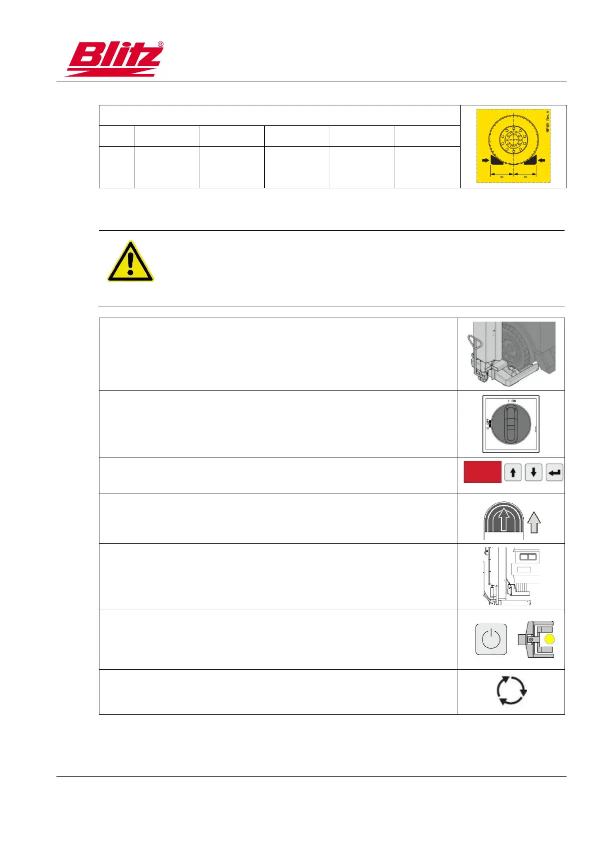
Wheel Ø at different setting positions of the wheel fork
10.5.3 Attach lifting units to the vehicle wheels
DANGER
Risk of death and injury from damaged tyres
◼ Never lift vehicles on damaged tyres.
◼ Never lift the vehicle on tyres with too low air pressure.
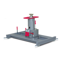
1. Push wheel fork under the wheel.
2. Switch on main switch.
3. Check or reset the transmission channel. (all lifting units of a
system must be set to the same channel) (→10.6)
4. Briefly raise the wheel.
5. Check the safe uptake of the wheel.
6. Mark the position of the lifting unit on the control and register for
group operation.
Repeat steps 1 to 6 for all lifting units.