EasyManua.ls Logo

BLOCKsignalling PPI4 - User Manual

BLOCKsignalling PPI4
6 pages
Print Icon
To Next Page IconTo Next Page
Loading...
POINTS POSITION INDICATOR PPI4
Advanced PPI with Adjustable Brightness & Simplified Wiring
Monitors the brief positive operating voltage across points motors when they are switched
Lights a corresponding led on a control panel to show the last operation of each set of points
Saves all settings automatically to memory when the power is switched off
Monitors up to 8 sets of points
Opto-isolated inputs accept voltages from +5V to +60V
The Points Position Indicator (PPI) monitors the brief switching voltage to either of the two
coils of a points motor, and displays the last operation using coloured leds which can be
mounted on a route mimic.
Manual methods to switch points include simple spring-loaded switches, push buttons, probe
and stud, etc and the points coils have a common connection to the ground of the supply.
When points are driven from DCC Accessory decoders, the decoders most often provide a
+12V supply to the common of the points coil, and then switch the other connections of the
coils to ground to switch the points (use PPI2-DCC with these).
Question and Answer IconNeed help?

Do you have a question about the BLOCKsignalling PPI4 and is the answer not in the manual?

Overview

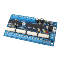
The BLOCKsignalling Points Position Indicator (PPI4) is a device designed to monitor the operational status of up to eight sets of points (railway turnouts) and display their last known position using colored LEDs on a control panel. This device is particularly useful for model railway enthusiasts who want a clear visual indication of their track layout's status.

Function Description

The PPI4 monitors the brief positive operating voltage that occurs across points motors when they are switched. It detects these voltage pulses to determine which coil of a points motor was activated, thereby inferring the new position of the points. For each set of points, the PPI4 can drive two LEDs (typically red and green) on a control panel mimic, with only one LED lit at any given time to indicate the most recent operation.

A key feature of the PPI4 is its ability to automatically save all settings to memory. This means that if the power supply is interrupted and then restored, the LED outputs will automatically revert to their last recorded condition, ensuring continuous and accurate display of points positions without manual reset.

The device is designed for systems where the common connection of the points motor coils is connected to ground. It utilizes a microprocessor to control LED brightness, eliminating the need for external resistors and simplifying the wiring process.

Important Technical Specifications

  • Monitoring Capacity: Monitors up to 8 sets of points.
  • Input Type: Opto-isolated inputs.
  • Input Voltage Range: Accepts voltages from +5V to +60V. This wide range makes it compatible with various points motor types and control systems.
  • Power Supply (for PPI4 operation):
    • DC Power Supply: 10V to 25V.
    • AC Power Supply: 10V to 16V.
    • Recommended Power Supply: 12V DC.
  • Power Supply (for LED operation): The PPI4 also requires a separate power supply for the LEDs, which must be in the range of 9V to 16V (AC or DC). If the points operate from a supply above 16V, the PPI can be powered from a separate 12V DC supply for the LEDs.
  • Channels: 8 channels, each with two inputs capable of driving two LEDs on the output.
  • Input Trigger Threshold: Inputs cause the associated output to switch when the input voltage rises above approximately 3V.

Usage Features

  • Simplified Wiring: The microprocessor controls LED brightness, so no resistors are required for the LEDs, simplifying the wiring process.
  • Compatibility with Manual Switching Methods: The PPI4 is compatible with various manual points switching methods, including spring-loaded switches, push buttons, and probe and stud systems, where the points coils have a common connection to the ground of the supply.
  • Compatibility with DCC Accessory Decoders: For points driven by DCC Accessory decoders that provide a +12V supply to the common of the points coil and switch the other connections to ground, the PPI2-DCC variant is recommended. The PPI4 is specifically designed for systems where the coil common is GROUND.
  • Visual Feedback on PCB:
    • YELLOW LED (IP): Flashes when a points change appears on any input terminal, confirming an input signal.
    • RED LED (uP): Flashes when the microprocessor records a change in any points position from that held in memory, indicating that the updated status has been stored.
  • LED Connection Guidance: Clear instructions are provided for connecting LEDs, emphasizing the importance of correct polarity (anode and cathode). The negative lead (cathode) is identified by a flat on the side of the LED body and a shorter lead.
  • Shared LED Outputs: Red and green LEDs share the same output. For instance, the first set of points uses a red and green LED with their anodes connected to terminal A1+. All green LED cathode connections go to the C1- terminal, and all red LED cathode connections go to the C2- terminal.
  • Power-Up Behavior: When powering up, the red (uP) LED on the PCB will light to indicate the microprocessor is running.
  • Factory Testing Clearing: After factory testing, it's possible for more than one LED to be lit initially. This condition will clear as soon as each set of points is operated for the first time.

Maintenance Features

  • Robust Design: Opto-isolated inputs provide electrical isolation, protecting the PPI4 from potential voltage spikes or noise from the points motor circuits.
  • Reverse Polarity Protection (for LED power supply): If a DC supply is used for the LEDs and connected in reverse, no harm will be done to the PPI4, though it will not function until corrected. This feature helps prevent accidental damage during installation.
  • Automatic Memory Storage: The automatic saving of points positions to memory eliminates the need for manual configuration or reset after power interruptions, contributing to a low-maintenance operation.

In summary, the BLOCKsignalling PPI4 offers a reliable, user-friendly, and robust solution for displaying points positions on a model railway control panel, featuring simplified wiring, broad compatibility, and intelligent memory functions.

BLOCKsignalling PPI4 Specifications

General IconGeneral
BrandBLOCKsignalling
ModelPPI4
CategoryMeasuring Instruments
LanguageEnglish