Do you have a question about the Blohm + Voss Oil Tools VES-HCL 350 and is the answer not in the manual?
Defines WARNING and NOTE for user safety and information.
Specifies the manual's purpose and target audience for service, engineering, etc.
Details the correct and incorrect usage of the tool, emphasizing rated load.
Outlines copyright and usage rights for the document content.
Explains compliance with EU directives and relevant machinery standards.
Details conditions under which the product warranty is voided.
Lists critical safety warnings covering ignition sources, proper use, PPE, and modifications.
Specific safety advice for elevator operation, including latching and pipe handling.
Guidelines for using bushing segments with correct serial numbers and pipe sizes.
Restriction on using the elevator without bushings, except for specific cases.
Importance of torquing link blocks for proper elevator latching.
Precautions for hydraulic operation and pressure release during maintenance.
Declaration of product conformity with relevant EU directives and standards.
Details the product marking and the specific standards it conforms to.
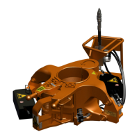
Overview of the Blohm+Voss VES-CL Elevator for drill pipe handling.
Specifies the elevator's primary purpose: handling vertical pipes.
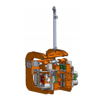
Lists the primary assemblies that constitute the Elevator 613000-Y-H-F.
Explains pipe placement, load transfer, and hydraulic cylinder actuation.
Describes the role of exchangeable bushings for accommodating different tubular sizes.
Explains the signal generated upon successful latching of the elevator.
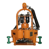
Lists key specifications including load capacity, part number, and operating parameters.
Specifies the range of pipe sizes compatible with the elevator's bushing system.
Details the screw couplings and hydraulic connections used on the elevator.
Describes the feedback signal that confirms the elevator is closed and latched.
Importance of identifying information for service and repair purposes.
Explains the step-by-step sequence for opening, closing, and handling pipes.
Provides detailed physical measurements (Length, Width, Height) of the elevator.
Explains the purpose of wear bushings in reducing elevator wear.
Details how to select, assemble, and tighten wear bushings correctly.
Visual representation of the elevator's complex hydraulic circuit.
Recommends official commissioning and reviewing the manual with the crew.
Procedure to cross-check all delivered parts against the scope of supply.
Verifies operating pressure and volumetric flow rates for the hydraulic system.
Essential checks and lubrication required before the elevator can be put into service.
Detailed tests to confirm elevator opening, closing, and feedback signal functionality.
Warnings and precautions to follow when lifting and moving the elevator.
Step-by-step instructions for physically connecting the elevator to the rig's elevator links.
Specifies the correct torque values for bolts and nuts during the installation process.
Provides a detailed diagram of the hydraulic system, including feedback loops.
Lists recommended hydraulic oils and their flash points for optimal performance.
Ensures controls maintain state after power loss and the use of isolation valves.
Explains the three main hydraulic connections (A, B, C) for closing, opening, and feedback.
Notes on bushing segments and essential safety checks before replacement.
Step-by-step guide for safely removing existing bushing segments from the elevator.
Detailed steps for cleaning, lubricating, and installing new bushing segments properly.
Checklist ensuring correct bushings, fixations, and feedback valve adjustment.
Verifies QD cleanliness and proper connection to the hydraulic power supply.
Checklist confirming elevator open/close functionality and signal presence.
Emphasizes hydraulic line isolation and coordinated operation with other equipment.
Step-by-step guide for safely running pipe into the wellbore using the elevator.
Step-by-step guide for safely tripping pipe out of the wellbore with the elevator.
Advises contacting Blohm+Voss for crack, wear, or welding issues.
Identifies specific points requiring daily greasing of the elevator components.
Lists key visual checks for components like latch, bolts, and feedback signal.
Recommends daily functional testing and removing faulty units from service.
Explains how screws are secured using mechanical locks or adhesives for safety.
Lists recommended grease types for effective lubrication across different temperatures.
Validates minimum ear dimensions against specific conditions for continued use.
Discusses normal wear, defects, and potential failures of bushings and elevator ears.
Step-by-step guide on using specialized gauges to check bushing wear.
Explains how to interpret gauge readings and determine necessary actions.
Explains measuring center bore diameter and using charts for tool joint compatibility.
Defines four distinct inspection categories based on scope and depth of examination.
Recommends inspection frequencies: Ongoing, Daily, 6 Monthly, and Yearly.
Details on-job, shut-down inspections required before/after critical operations.
Procedure for immediate inspection following critical loads or impacts.
Guidelines for dismantling and inspecting equipment upon return or before next job deployment.
Lists essential fields required on the checklist front page for accurate record-keeping.
Checklist for observing performance and identifying issues during normal operation.
Daily inspection checklist covering general issues, loose items, and potential damage.
Checklist for 6-month inspections, including NDT and part wear assessments.
Checklist for annual inspections, covering NDT, and component replacement needs.
Diagrams illustrating critical inspection points on the elevator's latch mechanism.
Diagrams highlighting critical areas of the hinge and latch assemblies for inspection.
Wear data criteria for body and latch hinge pins.
Wear data specifications for various wear bushing bore codes.
Lists checks for hydraulic connections, pressure, and control valve issues.
Lists checks for hydraulic connections, cylinders, and latch spring integrity.
Measures to protect the tool from moisture and prevent injury during storage.
Procedures for preserving the tool during short (up to 3 months) and long-term storage.
Instructions for safely lifting and transporting the elevator unit.
Lists bore codes associated with 18° DP sizes and their corresponding codes.
Lists bore codes for various tubing sizes and their corresponding identifiers.
Lists bore codes for drill collars featuring a zip groove.
Lists bore codes for drill collars without a zip groove.
Exploded view drawing of the VES HCL-350 Elevator with feedback system.
Parts list for the main assembly, mechanic kit, and hydraulic assembly.
Detailed diagram illustrating the basic components for hydraulic operation.
Comprehensive list of basic parts included in the 613005 unit.
Illustrates the components and assembly of the Mechanic Kit.
Lists all individual parts comprising the 613040 Mechanic Kit.
Schematic diagram of the hydraulic assembly with detailed component callouts.
Lists all components specifically for the 613056 hydraulic assembly.
Diagram of the HCL 350 elevator control manifold assembly.
Lists the parts used in the elevator control manifold assembly.
Schematic illustrating the various hose assemblies for the VES HCL 350.
Lists different hose assemblies with their part numbers and lengths.
Provides key dimensions and pressure ratings for the hydraulic cylinder.
Parts list for recommended spare parts for one-year operation of unit 613005.
Parts list for recommended spare parts for one-year operation of unit 613040.
Parts list for recommended spare parts for one-year operation of unit 613056.
| Brand | Blohm + Voss Oil Tools |
|---|---|
| Model | VES-HCL 350 |
| Category | Industrial Equipment |
| Language | English |