LED Relay Status Action
ON Closed Combined No Action
OFF Open Isolated No Action
Flash Open Isolated- Check Start Isolation
Start Isolation (SI) Wire
Flash Open Isolated-Under Combine Batteries Until Voltage is
Volage Lockout ≥ 10.9V @ 12V or ≥ 21.7V @ 24V
LED Status Chart
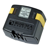
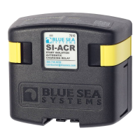
SI-Series*
Automatic Charging Relay (ACR)
*Start Isolation
990170140 Rev.007
Features
• Automatically combines batteries during charging, isolates batteries when discharging
and when starting engines
• Supports high-output alternators up to 120 Amps
• Ignition protected—safe for installation aboard gasoline powered boats
• Built-in LED light is ON when batteries are combined
• Allows temporary isolation of house loads from engine circuit during engine cranking to protect
sensitive electronics—start isolation indicated by blinking LED
• Under voltage lockout—will not close when the lower battery is below 10.8V @ 12V operation
or 21.6V @ 24V operation—lockout indicated by blinking LED
• Waterproof rated IP67----temporary immersion for 30 minutes
• Designed for 12 or 24 volt systems
• Dual Sensing—senses charge source on either battery bank
Guarantee
Blue Sea Systems stands behind its products for as long as you own them.
Find detailed information at www.bluesea.com/about.
For customer service, call 800-222-7617.
Specications 12VDC 24VDC
Continuous Rating 120A 120A
Intermittent Rating (5 min.) 210A 210A
Maximum Cable Size 1/0 AWG 1/0 AWG
Terminal Stud Size 3/8"-16 (M10) 3/8"-16 (M10)
Maximum Torque 140 in-lbs 140 in-lbs
RelayContactPosition
Combine (30 sec.) 13.6V DC 27.2V DC
(2 min.) 13.0 V DC 26.0V DC
Open Low (10 sec.) 12.35V DC 24.7V DC
(30 sec.) 12.75V DC 25.5V DC
Over Voltage Lockout 16.0V DC 30.0V DC
Under Voltage Lockout 10.8V DC 21.6V DC
RegulatoryE marked for Ignition Protection, Meets ISO 8846, UL 1500 and SAE J1171
external ignition protection requirements
Rated IP67----temporary immersion for 30 minutes
PN 7610
Marine Electrical Prod
ucts
InstallationInstructions
Mounting
• To avoid corrosion to connecting wires and terminals, mount in a dry and protected location
if possible. Avoid locations directly above the battery banks.
ElectricalConnections
• The wiring diagrams illustrated on the back page represent common installations and are not meant to
be a guide for wiring a specic vessel.
• The 7610 ACR is not intended to carry starting currents. Use a battery switching system with a
combine batteries/parallel function if batteries may need to be combined for emergency starting.
Caution:Disconnect battery connections before beginning the installation.
Use the wire sizing chart below to select the appropriate wire sizes to prevent overheating the ACR.
WireSizeandFuseRatingChart(AWG)
ChargingAmps MinimumWireSize* FuseRating
≤60 #6 75-90A
≤80 #4 100-125A
≤100 #2 150A
≤120 #1 175A
VoltageSensing
• The 120 Ampere SI ACR (7610) will sense charging sources available on either battery bank.
Minimumconnectionsforoperation:
• Connect one battery bank to stud terminal A.
• Connect the other battery bank to stud terminal B.
• Connect the quick connect terminal marked GND (ground) to the DC system ground through
a ten to fteen amp in-line fuse to prevent fault currents from owing in this wire.
1.StartIsolation(SI)Wire
• The 7610 ACR can be congured to automatically disconnect when the starting circuit is engaged.
Enable this feature to isolate the start circuit from the house circuits and prevent starting currents from
owing through the ACR or starting current transients from interfering with loads on other batteries.
The reaction time of the 7610 ACR is fast enough to disconnect the battery banks before the
starting current rises in the starting circuit.
2.Remoteindicatorlamp– mirrors “COMBINED” LED on unit.
• Appropriate 12/24V LEDs include Blue Sea Systems PNs 8033 (amber), 8171 (red), or 8172 (green).
ToconnectaremoteLEDindicator:
• Connect the red wire of the LED to a 12/24V positive source through a 2A inline fuse.
• Connect the yellow wire of the LED to the quick connect terminal marked LED.
Open/CloseCycling
• If your electrical system is congured with a charging source that cannot supply the full load current
being drawn from the receiving batteries, an open/close cycling process can occur. If this cycling
continues, the second battery bank could eventually discharge even though a charge source
is present.
Optionalconnections:
* Larger wire sizes may be
required to minimize voltage
drop in long wire runs.
For more information please
use the Circuit Wizard at
www.circuitwizard.bluesea.com.
Toenablestartisolation:
• Connect a wire from the quick connect terminal marked SI (starting isolation) to the
terminal or wire running from the start key switch to the starter solenoid. Make this
connection through an in-line fuse of 1 to 10 Amps. This connection can be made at the
start key switch or at the starter solenoid, but must be to the line that is positive only when
cranking. Connection to a line that is positive while the engine is normally running will
prevent the charging relay from working properly.