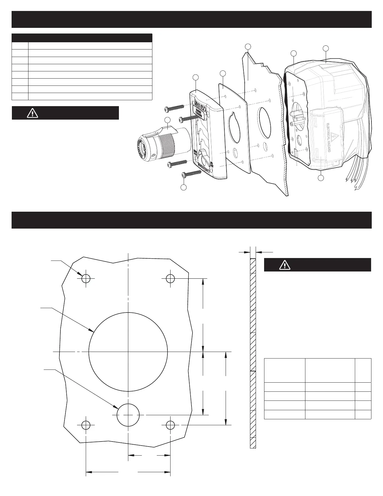
Installation and Mounting Diagram
Item Description
1 Installation Screws #8-32 (4 packs included)
2 Cover
3 Gasket* Note: Qty. 2 included
4 Vehicle wall / mounting surface
5 Ejection unit
6 AC/DC termination cover
7 Connector 120V AC
8 Weather-resistant boot
Do not use screws that will penetrate the
Ejection Unit’s mounting holes deeper
than 3/8
".
If vehicle wall / mounting surface material is
less than 1/8" thick, shim with extra
1/16" thick gasket (included).
NOTE: Four screw packs are included. Choose
the appropriate screw length for your Vehicle Wall /
Mounting Surface Thickness. (see table below).
Cutout Template
4
3*
2
1
7
#8-32 Installation Screws
Max. Torque 11 In-lbs
5
6
8
C
L
C
L
4X Ø .188"
(4.7mm)
CLEARANCE
FOR
#8 SCREWS
THRU
1.625"
(41.2mm)
1.625"
(41.2mm)
1.40"
(35.5mm)
.938"
(23.8mm)TYP
1.875"
(47.6mm)
Ø.50
(12.7mm)
Ø1.75 THRU
(44.4mm)
.125" (3.17mm)
Minimum
MOUNTING SURFACE
1. Sure Eject must be mounted vertically (+/- 15º)
as shown, and in a nominally dry and
protected location.
2. Connected wiring must include appropriate
drip and service loops.
3. If ejection unit (Item 5) is mounted externally or
exposed to weather elements, installation with
weather-resistant boot (included) is recommended.
a. Route wires through hole in cover.
b. Slide weather-resistant boot over ejection unit, wires exit at bottom.
c. Install Sure Eject.
d. Use heat gun to shrink cover in place before or after installation.
Visit bluesea.com for more information.
Vehicle Wall /
Mounting Surface
Thickness
Screw Length
Screw
Pack #
1/8" (3.2mm) #8-32 x 1.0" (1") 1
1/4" (6.4mm) #8-32 x 1.125" (1-1/8") 2
3/8" (9.5mm) #8-32 x 1.25" (1-1/4") 3
1/2" (13mm) #8-32 x 1.375" (1-3/8") 4
CAUTION
Warranty void if incorrect
screw length is used.
CAUTION
 Loading...