This document provides service training for Blueair appliances, covering parameter control guidance for R-290 reach-in and undercounter refrigerators/freezers, and installation and parameter control for modular ice machines.
R-290 Reach-ins and Undercounters Parameter Control
Function Description
The R-290 units are refrigerators and freezers equipped with a digital display for temperature control and status monitoring. They utilize R-290 refrigerant. The display shows the internal temperature and various operational icons indicating defrost cycles, fan operation, compressor status, and temperature units (°F or °C).
Important Technical Specifications
- Default Set Temperature:
- Refrigerator: 35°F (2°C)
- Freezer: 0°F (-18°C)
- Temperature Control Range:
- Refrigerator: 33°F (0.5°C) ~ 39°F (3.9°C)
- Freezer: -10°F (-23.3°C) ~ 5°F (-15°C)
- Compressor Start Delay: 5 minutes after power connection to prevent damage.
Usage Features
- Temperature Display: Shows the internal temperature.
- Temperature Control Buttons: Used to adjust the temperature settings.
- Lock Button: Used for adjustment confirmation and control panel locking.
- Icon Indicators:
- "DF": Defrost activated.
- Fan icon: Evaporator fan(s) in operation.
- Compressor icon: Compressor in operation.
- °F/°C icons: Toggle between Fahrenheit and Celsius display.
- Error Check Mode:
- Press the lock button for 3 seconds.
- Press the up arrow button for 5 seconds until "no" or an error code is displayed. "no" indicates no errors.
- Press the down arrow button to check for additional error codes.
- Exit by not touching the controller for 15 seconds.
- Test Mode:
- Press the lock button for 3 seconds.
- Press the down arrow and up arrow buttons together until "nd" is displayed.
- Press the down arrow button 18 times until "tE" is displayed.
- "St" will be displayed after a "Beep" sound.
- Press the up arrow button to check each part's operation.
- Exit by returning to "St" and not touching the controller for 15 seconds.
Maintenance Features
- Error Codes:
- 1-1. "S1": Defective Temperature (Room) Sensor: Sensor disconnected, open, or cabinet temperature below -58°F.
- 1-2. "S1_": Defective Temperature (Room) Sensor: Sensor shorted or cabinet temperature above 149°F.
- 2-1. "d1": Defective Defrost Sensor: Sensor disconnected, open, or cabinet temperature below -58°F.
- 2-2. "d1_": Defective Defrost Sensor: Sensor shorted or cabinet temperature above 149°F.
- 3. "Df1": Fail to Defrost: Defrost time exceeds 50 minutes.
- 4. "CF1": Fail to Cool: Defrost sensor reads 32°F or above after 30 minutes of compressor operation.
- 5. "EHF" (Freezer Only): Cabinet Temperature is High: Cabinet temperature above 45°F for 8 hours after compressor startup.
- 6. "EHr" (Refrigerator Only): Cabinet Temperature is High: Cabinet temperature above 45°F for 8 hours after compressor startup.
- 7. "Edr": Door is open more than an hour.
- 8. "UFN": V-FAN is disconnected (Top Mount Refrigerator Only).
- Test Codes (for diagnosing components):
- 1. "CP1": Turns on the compressor and fans.
- 2. "dHt" (Freezer Only): Turns on the defrost heater.
- 3. "CHt" (Not in use for "-HC" units): Turns on the cord heater.
- 4. "LP": Turns on the LED light.
- 5. "FS": Checks temperature (room) sensor. Displays cabinet temperature if okay, "to" or "ts" if defective.
- 6. "rt": Checks ambient temperature sensor on control board. Displays cabinet temperature if okay, "to" or "ts" if defective.
- 7. "ds": Checks defrost sensor. Displays cabinet temperature if okay, "to" or "ts" if defective.
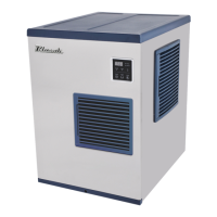
Ice Machines Parameter Control
Function Description
Blueair ice machines feature a control panel with a display and buttons for power, wash, and check functions. It monitors and controls various cycles including water supply, harvest, and freeze, and indicates operational status and errors.
Important Technical Specifications
- General Requirements:
- Ambient Temperature: 45°F (7°C) to 100°F (38°C)
- Water Temperature: 45°F (7°C) to 90°F (32°C)
- Water Pressure: 30 psig (206.8 kPa) to 100 psig (689.4 kPa)
- Voltage: 115V (100-130V) or 220V (208-230V) depending on model.
- Water Inlet: 3/8" FPT, ID 1/4" copper pipe (Min.)
- Drain: 3/4" FPT, ID 3/4" Hard pipe (Min.)
- Clearance: Must maintain 8" minimum clearance at each side for proper air circulation.
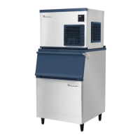
- Modular Ice Machine Installation:
- Valve Opening: Both internal valves (for BLUI-250A, BLMI-300A/500A/500AD/650A/900A) must be opened prior to operation. These are located in the back panel (undercounter) or inside the unit (modular).
- Leveling: Modular unit and storage bin must be leveled.
- Bin Switch: Install bin switch and thumbscrews (found in a bag near the compressor).
- Water Supply & Drain Lines: Maintain a 2" vertical air gap between pipe ends and the floor drain.
- Wiring: BLMI-650A/900A models include a built-in voltage transformer.
Usage Features
- Display Indicators:
- "1.00": Water Supply Cycle (elapsed time in x 10 sec).
- "2.00": Harvest Cycle (elapsed time in min).
- "3.00": Freeze Period (elapsed time in min).
- "FUL": Ice storage bin full.
- "drA": On drainage.
- "CLn": On cleaning.
- "Add": On cleaning (to put cleaner or sanitizer into water trough).
- "End": Cleaning or sanitization completed.
- Status LED Lamp: Indicates Freeze, Harvest, On/Off, Clean, and Error status.
- Ice Machine Status Check (Press "Check" button while on):
- "E": Real-time evaporator temperature.
- "F": Average time of freezing cycle.
- "H": Average time of harvest cycle.
- "三": Total freezing cycle counts.
- Test Mode:
- Press "Power" button for 5 seconds to turn off the machine.
- Press "Wash" button for 5 seconds to activate test mode.
- "OFF" will be displayed.
- Press "Wash" button to check each component.
- Press "Wash" button until "OFF" is displayed again.
- Press "Wash" button until the display goes black to exit.
- Additional Functions:
- Manual Harvest: Press "Power" and "Wash" buttons together while the unit is on.
- Manual Drainage: Press "Wash" button once while the unit is off.
- Vacuum (Opening all valves to expedite service time): Press "Wash" and "Check" buttons together while the unit is off.
Maintenance Features
- Error Codes:
- 1. "E1": Freezing problem: Freezing cycle exceeds 60 minutes twice in a row.
- 2. "E2": Harvest problem: Harvest cycle exceeds 25 minutes twice in a row.
- 3. "E3": Evaporator temperature problem: Evaporator sensor temperature is over 140°F (60°C). (Note: Generally under 120°F (49°C)).
- 4. "E4": Drain problem: Water is not drained during full storage. Press "Power" to turn off the alarm.
- 5. "E5": Water supply problem: Water level sensor detects insufficient water, or water supply time exceeds 4 minutes.
- 6. "E6": Evaporator sensor problem: Evaporator sensor is damaged or disconnected.
- 7. "E7": Main control board problem: Main control board not operating properly.
- Refer to service manuals for recommended resolutions.
- Test Codes (for diagnosing components):
- 1. "C": Turns on Compressor, Fan Motor, and Liquid Valve.
- 2. "P": Turns on Pump Motor to C.W. (Water Supply).
- 3. "P1" (Modular only): Turns on Pump Motor to C.C.W. (Drainage).
- 4. "H": Opens Hot Gas Valve.
- 5. "F": Turns on Fan Motor.
- 6. "三": Opens Water Valve.
- 7. "AC": Opens Cleaning Valve.
- 8. "AS": Opens Liquid Valve.
- 9. "d": Drains the water.
- 10. "Dyc" (Factory use only): Opens Water Valve, Cleaning Valve, Drain Valve.
- Note: Test mode only shows available parts for each machine. If a part is not present, its test code will not display.