This document is a use and maintenance manual for a series of wheeled brushcutters manufactured by Bluebird Industries. The models covered are:
- FLO Speed 6BS / 7BS
- FLO Speed 6HO / 7HO
- FLO Pro Speed 6HO / 7HO
- FLO Speed 6LC / 7LC
The manual is provided in English and is Rev. 1.0.
Function Description
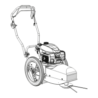
The machine is designed to cut grass and small shrubs in agricultural or forest environments. It is driven by a single competent operator and is intended for use in slope conditions specified by the engine manufacturer, ensuring the operator can maintain control with a good safety margin. The machine's protections are designed to ensure the operator's safety from direct projection of stones or other objects from the rotating system. The operator must always remain in the normal driving position, behind the machine, with both hands firmly on the handles.
Important Technical Specifications
The manual outlines various technical aspects and specifications, particularly concerning safety and maintenance.
Sound Power Levels (per 2000/14/EC (2005/88/EC) – Annex V):
- FLO Speed 6/7 BS: Measured 108 dB / Guaranteed 114 dB LWA
- FLO Pro Speed 6/7 BS: Measured 110 dB / Guaranteed 114 dB LWA
- FLO Speed 6/7 HO: Measured 109 dB / Guaranteed 114 dB LWA
- FLO Pro Speed 6/7 HO: Measured 110 dB / Guaranteed 114 dB LWA
- FLO Speed 6/7 LC: Measured 110 dB / Guaranteed 114 dB LWA
Standards Compliance:
The product complies with directives 2006/42/EC, 2014/30/EU, 2000/14/EC (2005/88/EC), and 2011/65/EU. It also conforms to standards EN ISO 12100:2010, UNI EN 12733:2019, and ISO 11684:1995.
Cutting Devices:
The machine is sold with a line cutting device but can also be equipped with a blade cutting device, which can be purchased separately. The blade cutting device is suitable for cutting thick grass and brushwood, shredding vegetation left on the ground, and ensures compliance with Community standard EN12733.
Usage Features
Machine Preparation:
The machine is delivered assembled, with the handlebar folded for transport. To prepare for use, the handlebar (1) needs to be opened. This involves loosening two side knobs (2) to allow the handlebar to rotate, adjusting its inclination (B), and then tightening the knobs (C) to secure it in the optimal working position. For some models, there's an additional step to adjust the horizontal rotation of the handlebar by loosening a fastening lever (3), adjusting rotation (E), and then tightening the lever (F).
Controls Operation:
- Starting the Engine: Move the gas control lever (1) to the "START-MAX" (A) position. Press the fuel primer bulb on the engine carburetor and pull the starter cord (2) until the engine starts.
- Stopping the Engine: Move the gas control lever (1) to the "MIN-STOP" (B) position.
- Activating the Cutting Device: Lift (A) and move (B) the safety hook (2) to deactivate it, then pull the cutting device control lever (3) towards you (C).
- Deactivating the Cutting Device: Release (D) the cutting device control lever. A safety brake stops the cutting device within a few seconds, but it's not instantaneous. The operator must remain in the driving position until the disc is perfectly still. The safety hook is crucial for two-handed operation, preventing accidental activation.
- Self-propelling Operation: Select the desired speed (1-slow, 2-intermediate, 3-fast) using the speed knob (4) on the rear of the machine. Push the forward motion control lever (5) forwards (B) towards the handlebar to engage automatic forward motion. Release the lever to stop. The machine has a "free wheel" system for maneuverability, meaning traction cannot be used as a brake on uneven surfaces.
Safety Instructions:
Operators must read the manual carefully. Personal protective equipment (PPE) is mandatory: close-fitting overalls, closed work shoes with non-slip soles, protective helmet (if risk of falling objects), visor/anti-fog goggles, earmuffs/earplugs, and work gloves. Children and untrained individuals must not operate the machine. Fueling operations must be done outdoors, without smoking, and with a cool engine. In case of fuel leaks, the engine must not be started until spilled fuel has evaporated. Regular checks of cutting devices for damage or wear are essential.
Maintenance Features
General Maintenance:
Inspections and operations requiring specific technical skill and equipment should be performed by a retailer or qualified assistance center. Before any maintenance, the engine must be switched off, the spark plug disconnected, and starting keys removed (for electric start models). Protective gloves and suitable equipment must be used.
Engine and Lubrication:
- Technical Assistance: For engine-related technical assistance or warranty requests, contact authorized service centers for Briggs & Stratton (www.rama.it) or Honda (www.honda-engines-eu.com).
- Engine Oil: Check engine oil level before each use and top up if necessary, referring to the engine's operating manual.
- Reduction Gear: Does not require topping up.
- Transmission Chain: Clean and lubricate the transmission chain with gas oil or suitable detergent during long idling periods, taking precautions for flammable materials.
Adjustments:
- Cable Tension: Cables are adjusted by moving the adjuster on the handlebar's thrust plate to lengthen or shorten the cable.
- To Increase Cable Tension: Remove protective cap (3), slacken nut (4), push adjuster (5) downwards until nut (4) rests on the thrust plate, tighten nut (6) against the thrust plate, and reinsert protective cap (3).
- To Slacken Cable Tension: Remove protective cap (3), slacken nut (6), push adjuster (5) upwards until nut (6) rests on the thrust plate, tighten nut (4) against the thrust plate, and reinsert protective cap (3).
- Cutting Device Coupling Control Transmission: Adjust belt tension if there are signs of sliding (ineffective cutting, smoke, screeching) or if the cutting device remains coupled when the lever is released. Stretch the cable to increase tension or slacken it to reduce tension. If cable adjustment is insufficient, modify the tension by adjusting the cutting belt center distance.
- Feed Coupling Control Transmission: Adjust cable tension if traction is not coupled or remains coupled after the lever is released. Increasing tension applies greater force, while slackening reduces it.
- Cutting Belt Centre Distance Adjustment: If the transmission belt lengthens over time, causing power loss or slipping, slacken the four nuts (7) fastening plate (8), then move plate (8) forwards or backwards to achieve the desired tension. An overly tight belt is dangerous, while a slack belt will slip and deteriorate. The correct play is approximately 10 mm distance between the two belts when the machine is off.
- Blade Brake Shoe: If braking capacity is inadequate, adjust the brake shoe (9). Switch off the machine, remove the protective nose, and check if the brake shoe is providing braking. Slacken cable tension using the handlebar adjuster or tensioner (10). Operate the red lever to check if the brake shoe (9) contacts the clutch pulley (11). Press the red lever to ensure the brake shoe (9) releases the pulley for operation. The brake shoe is correctly adjusted when the device brakes within 5 seconds for the blade and 3 seconds for the cutting wire.
Cutting Device Assembly/Disassembly:
- Disassembling the Line Cutting System: Loosen fixing screw (A) with an 8 mm Allen key (6) and remove cutting unit (7) (B). To remove the nylon guard (8), slacken rear fixing screws (9) (A), remove front screws (10) (B), and then remove the guard (8) (C).
- Assembling the Line Cutting System: Insert upper guard (8) onto blade hub (11) and rear fixing screws (9) (A). Fix the guard to the front attachment by tightening screws (10) (B), then tighten rear screws (9) (C). Insert cutting disc (2) onto cup (4) (D). Thread fixing screw (5) into the cutting cup (E). Insert the entire assembly onto the cutting system mount and tighten the screw (F). Ensure the cup pin and support pin correctly enter the cutting disk hole to avoid damage.
- Replacing Cutting Elements (Nylon Line): Rotate cutting disk (2) until fixing slots (12) are accessible. Apply line (13) as shown, adjust ends to equal length, and tighten the knot by pulling both ends. Only use manufacturer-supplied cutting elements; metallic elements are prohibited.
- Blade Device Assembling: This operation requires care and should be done by trained personnel. Disconnect the spark plug cap. Lift the front of the machine (1), supporting it on the handlebar ends (2) (A). Disassemble the line cutting device (3) (B). Place the blade guard (4) under the mower unit/machine frame (5) (C). Insert fixing screws (6) onto the mower unit without fully tightening (D). Slide the blade guard (4) through the two slots on the partially tightened screws (E). Attach the blade guard with screws (7) under the mower unit/machine frame (F). Tighten front screws (7) fully (G), then rear screws (6) (H). Insert spring washer (13) then lock washer (14) onto blade fixing screw (12). Fit blade (8) between cutting device (9) support and blade centring flange (10). Secure the blade with screw (12) and washers (13, 14), ensuring the sharpened edge faces the ground. Carefully tighten the blade locking screw (12). Manually rotate the blade to check for contact with other parts. Fix the slide (15) on the blade guard with screws (16), washers (17), and nuts. Adjust cutting height using the slide's side holes. Lower the machine (I) onto the slide and reinsert the spark plug cap (L). The blade edges are sharp, so heavy gloves are required.
Troubleshooting Cutting Issues:
If the cutting device bogs down in very high or wet grass, the engine may lose revs, the belt may screech, or smoke may emerge. To address this: advance at minimum speed (or disengage traction and push), slightly lift the front of the machine, adjust cutting height to a higher position for initial passes, or stop forward movement, raise the front of the machine to release the blade, then resume cutting. If the engine stalls, stop the feed and cutting device, remove the spark plug cap, and manually clear accumulated grass (wearing gloves). Do not continue working or try to free the blade by coupling/decoupling traction. Check belt tension if it slides in short grass.
Impact with Obstacles:
If the blade impacts an obstacle, switch off the engine, remove the spark plug, and inspect for broken or damaged parts. Replace with original spare parts if necessary, and properly tighten screws and locking nuts. Check for strange vibrations or noises once the machine is in motion. Consult a service center if problems persist. Ensure protectors are in perfect condition.
Transport and Storage:
For transport or storage, the handlebar can be folded (A) by slackening fastening knobs (1) (B), ensuring cable bend radii are not excessively small. The machine must be lifted by at least two people, holding it from the sides. Never store the machine with fuel in the tank inside a building where vapors could reach flames or sparks. Cool the engine before storage. Store in a dry, ventilated place, covered with a cloth, inaccessible to unauthorized people. Prevent fuel stagnation for long periods.
Warranty:
Bluebird Industries guarantees correct operation for 24 months (12 months for professional use) from purchase date (sales receipt/invoice). Warranty covers free replacement of mechanical/electrical components due to manufacturing/material defects. Technical staff will restore the product promptly. Warranty is limited to replacement of defective parts/repair of faults within two months of discovery. Normal wear parts (cutting discs, knives, spark plugs, etc.) are excluded. Replaced faulty components are retained by Bluebird. Free replacements do not extend payment terms. During warranty, machinery must not be sold permanently in use, sold, or exported. Bluebird disclaims liability for damage from improper use, even for warranted machines. Warranty does not cover setup, maintenance, updates, or improvements. Warranty is void for lack of maintenance, incorrect use, tampering, unsuitable lubricants/fuels, non-original spare parts, or unauthorized work. Engines from other brands (Kawasaki, Honda, Briggs & Stratton) are covered by their respective manufacturers' warranties.