Do you have a question about the BlueSun SG600 Series and is the answer not in the manual?
Key features and benefits of the SG600 PV microinverter.
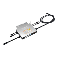
Diagram illustrating the physical components and connection points.
Technical drawings showing the physical size and measurements.
Diagram for connecting SG600 microinverters to a 120V single-phase grid.
Diagram for connecting SG600 microinverters to a 2-phase grid.
Diagram for connecting SG600 microinverters to a 230V single-phase grid.
Wiring diagram for 230V single-phase grid connection.
Wiring diagram for 120V single-phase grid connection.
Wiring diagram for 2-phase 208/240V grid connection.
Wiring diagram for 3-phase 380V grid connection.
First wiring diagram for 3-phase 208/240V grid connection.
Second wiring diagram for 3-phase 208/240V grid connection.
Important safety and setup information before configuration.
Overview of the microinverter's physical components and indicators.
Explanation of the LED indicator states for WiFi status.
Steps required before starting WiFi cloud monitoring setup.
Answers to common questions regarding app connectivity and configuration.
Initial steps for configuring the microinverter's WiFi connection.
Process of adding the microinverter to the Smart Life app.
How to change the name of the configured microinverter.
Steps to delete a microinverter from the app.
Instructions for sharing inverter access with other users.
Diagrams showing the pinout of AC connectors for the bus cable.
Diagrams showing the pinout of AC connectors for the bus cable.
| Operating Temperature Range | -20°C to +65°C |
|---|---|
| Cooling | Natural Convection |
| Communication | PLC, Zigbee |
| Enclosure Rating | IP65 |
| Operating Temperature | -20°C to +65°C |
| Model | SG600 Series |