7. Note, The landing gear on the Ultimate
are swept rearwards. In other words,
they slant towards the rear of the
airplane when viewing from the side.
Keeping this in mind identify the right
and left gear legs and wheel pant
assemblies. Take one assembly and
push the axle threads through the axle
hole in the aluminum landing gear and
install the other flanged nut to secure it
to the landing gear.
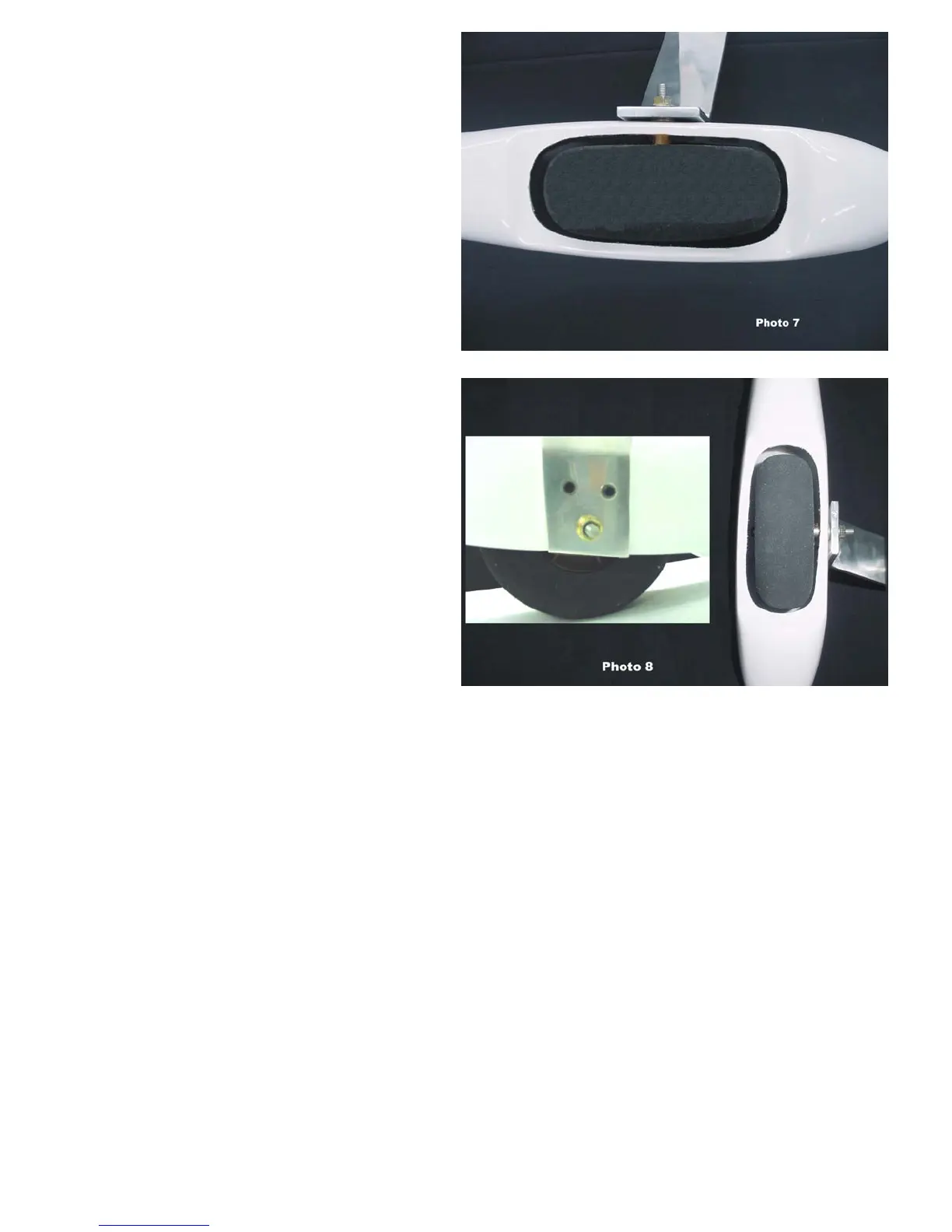
8. Mount the wheel pants to the landing
gear legs using the screws provided.
There are 2 screws for each wheel pant
and the holes have already been drilled
in the pants and the blind nuts have
already been installed at the factory
9. The axle will need to be adjusted
inward/outward in order to position the
wheel in the cut out. The adjustment is
performed by screwing the axle in and
out of the landing gear leg using a
Phillips screwdriver through the hole in
the outer wheel pant side. Once it is in
the correct position the wheel collar may
be tightened to secure the wheel in the
proper location. The wheel is captured
by the screw head of the axle on one
side and the wheel collar on the other
side.
10. Check all clearances to ensure that the wheels will not rub against the cut outs. If more clearance is
required enlarge the cut outs using a Dremel tool (use a mask!). When everything fits correctly and
there is adequate clearance between the wheel and wheel pant, tighten the axle nuts securely. It is a
good idea to use a thread-locking compound such as red Loctite to prevent the axle nuts from
coming loose.
BME 37% Ultimate Ver 1.0 3/15/2004 Page 6
 Loading...