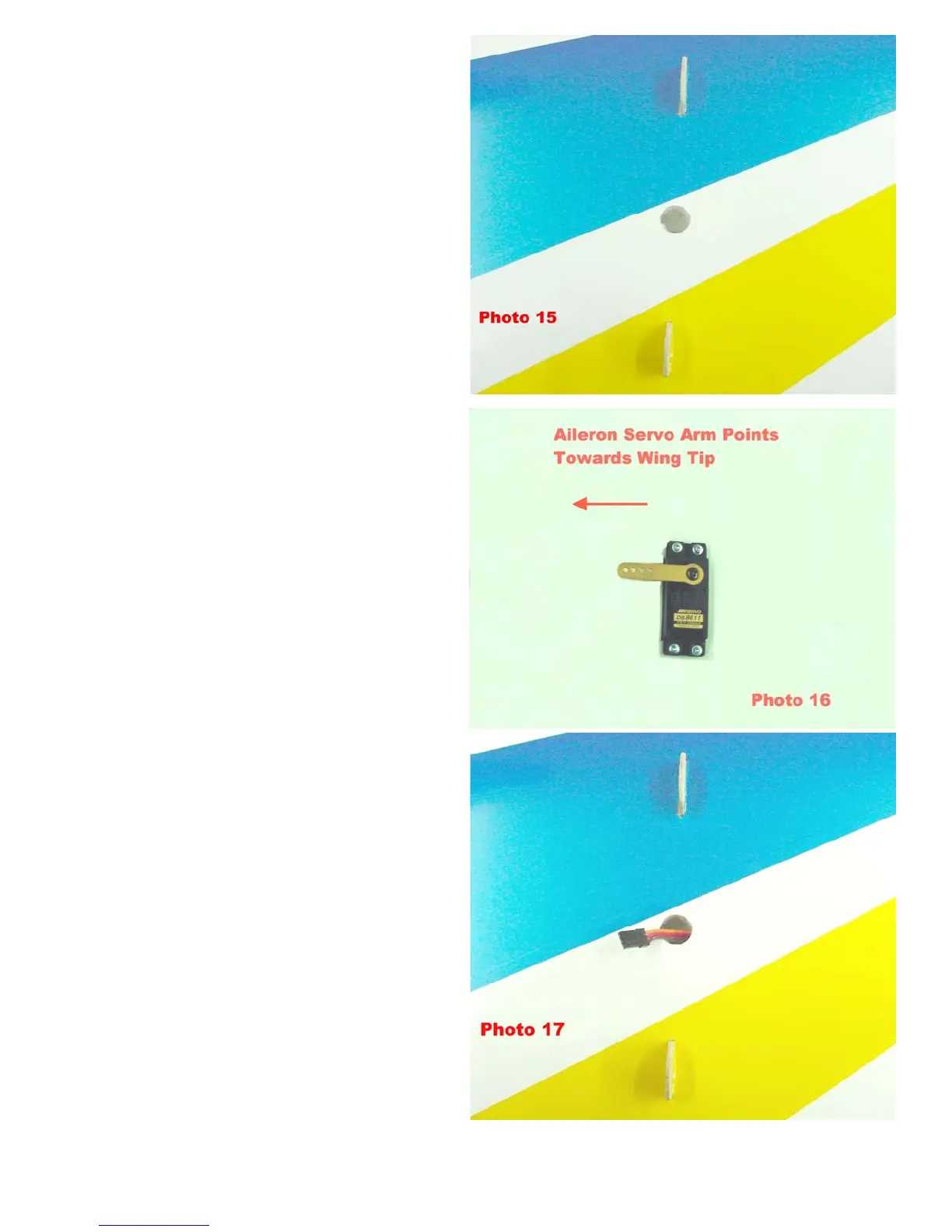
2. Locate the servo lead exit holes on the
top of the bottom wing between the two
strut mounting tabs. Cut the covering
over the holes and use a trim iron to tuck
the covering down into the holes as
shown in photo 15. These holes are
where the servo extensions for the servos
in the top wing panels will be connected
as they pass up through the wing struts on
their way to the servos in the top wing
panels.
3. Thread 2 servo extensions through each
bottom wing panel from the wing root.
One extension exits the hole in the top of
the wing panel, which will later be
connected through the strut to the servo in
the top wing panel. The 2
nd
extension is
plugged into the servo in the bottom wing
panel. Mount the aileron servos in the
bottom wing panels after running both
extensions through each panel. See
photos 16 & 17. Note: All aileron servo
arms must point towards the wing tips in
order to line up with the hard points
embedded in the ailerons.
BME 37% Ultimate Ver 1.0
3/15/2004 Page 9
 Loading...