G01�General�Vehicle�Electronics
12.�Horn
48
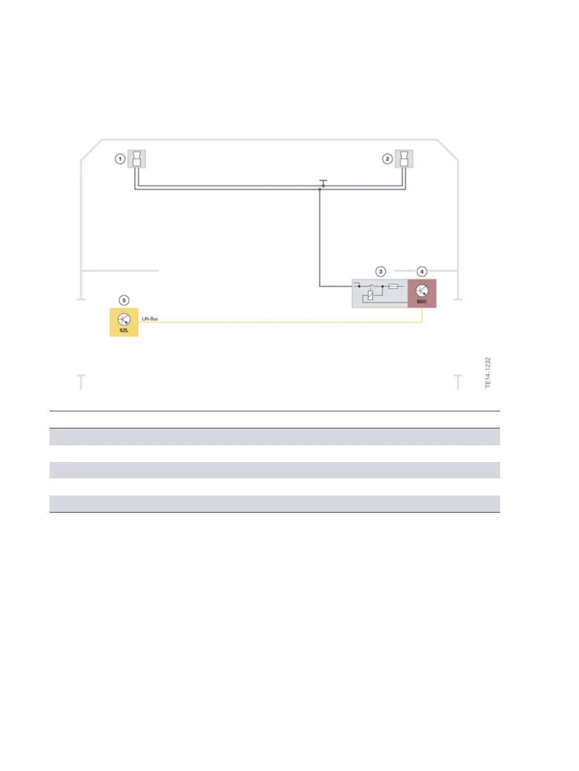
12.1.�System�wiring�diagram
Horns
Index Explanation
1 Horn,�left
2 Horn,�right
3 Relay�in�the�Body�Domain�Controller
4 Body�Domain�Controller�(BDC)
5 Steering�column�switch�cluster�(SZL)
Signal�path�of�horn:
• The�horn�button�is�read�in�by�the�steering�column�switch�cluster�(SZL).
• The�SZL�sends�the�information�via�the�local�interconnect�network�bus�to�the�Body�Domain
Controller.
• The�Body�Domain�Controller�evaluates�the�information�and�activates�the�relay�for�the�fanfare.