16
© 2005 Directed Electronics, Inc.
If the vehicle requires more than one ignition as per the Web site
information follow the same test procedure and solder the thick
PINK/WHITE (F) relay wire to it and be sure to wrap the
connection with electrical tape. If your vehicle has only 1 igni-
tion source, secure the PINK/WHITE out of the way.
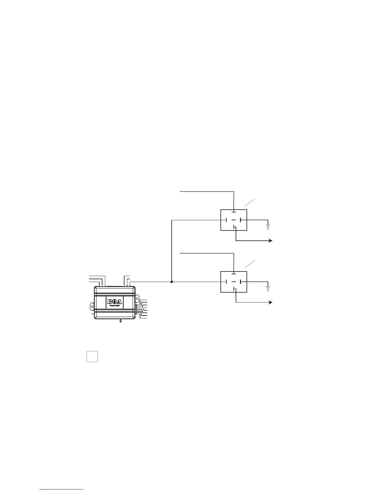
If your vehicle requires more than two ignitions, an additional
relay (not provided) is required. Refer to the diagram below.
step 3
Accessory and Starter wires
The starter and accessory wires will be located in the same harness
as the ignition and constant power.
➜
 Loading...