17
© 2005 Directed Electronics, Inc.
To find the accessory wire leave the LED tester black lead
connected to the metal ground, take the red lead and probe the
wire suspected to be the accessory. With the key off, your LED
tester should not illuminate. Turn the key to the on position and
the LED tester should be illuminated. Now turn the key to the
crank position. If you have the correct accessory wire the voltage
will disappear while the starter is cranking and return once the key
returns to the on position. If the wire tests correctly, strip the insu-
lation off a small portion and solder the thick ORANGE (C) relay
wire to it and wrap it with electrical tape.
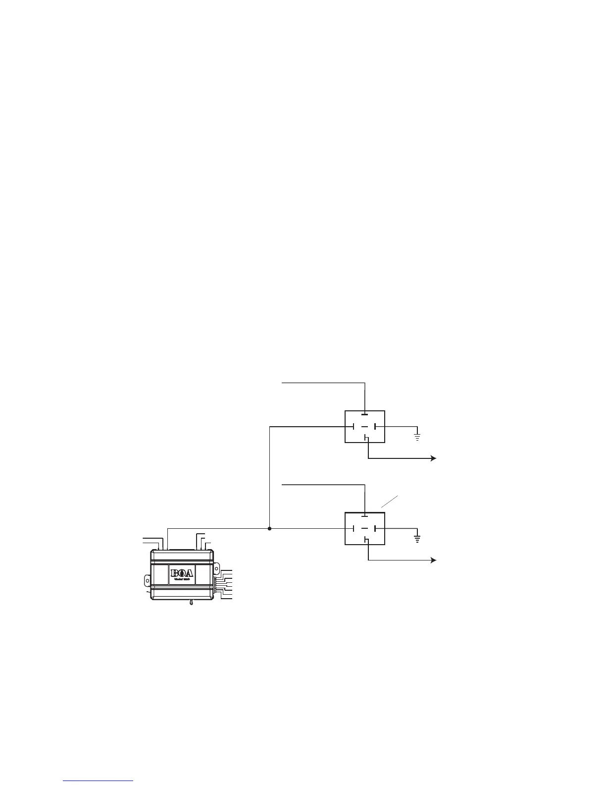
If your vehicle requires more than one accessory, an additional
relay (not provided) is required. Refer to the diagram below.
 Loading...