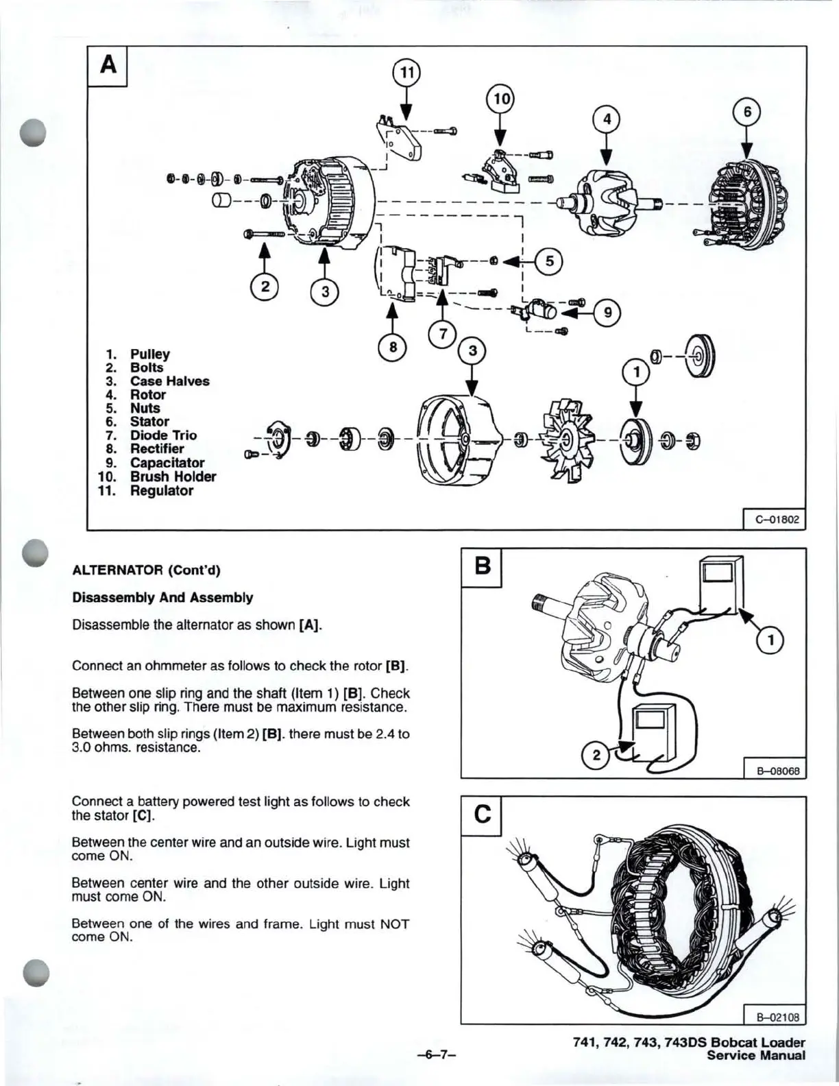
A
1.
2.
3.
4.
5.
6.
7.
8.
9.
10.
11.
Pulley
Bolts
Case Halves
Rotor
Nuts
Stator
Diode Trio
Rectifier
Capacitator
Brush
Holder
Regulator
ALTERNATOR (Cont'd)
-~-~--ID--~-
--
(]p_\~
Disassembly
And
Assembly
Disassemble the alternator as shown [A].
Connect
an
ohmmeter as follows to check the rotor [B].
Between one slip ring and the shaft
(Item 1) [B). Check
the other slip ring. There must be maximum resistance.
Between both slip rings
(Item 2) [B]. there must be 2.4 to
3.0 ohms. resistance.
B
Connect a battery powered test light as follows to check C
the stator [C).
Between the center wire and
an
outside wire. Light must
come
ON.
Between center wire and the other outside wire. Light
must come
ON.
Between one of the wires and frame. Light must NOT
come
ON
.
~7-
G--01802
D
B-<l8068
741,742, 743, 743DS
Bobcat
Loader
Service Manual



 To Next Page