CYLINDER HEAD (Cont'd)
Valve
Guide Installation (Cont'd)
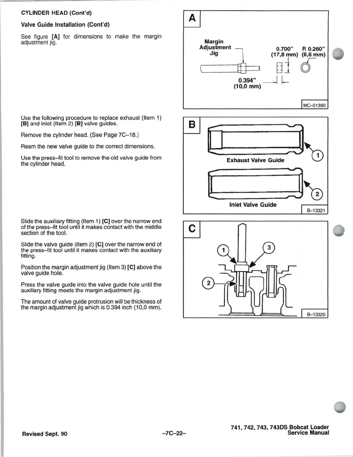
See figure
[A]
for dimensions to make the margin
adjustment jig.
Use the
following procedure to replace exhaust (Item 1)
[B) and inlet
(Item 2) [B) valve guides.
Remove the cylinder head. (See Page
7C-18.)
Ream the new valve guide to the correct dimensions.
Use the press-fit tool to remove the
old valve guide from
the cylinder head.
A
B
Slide the auxiliary fitting (Item 1) [C) over the narrow end
of the press-fit tool until it makes contact with the middle
C
section of the tool.
Slide
the valve guide (Item 2) [C) over the narrow end of
the press-fit tool until it makes contact with the auxiliary
fitting.
Position the margin adjustment jig
(Item 3) [C) above the
valve guide hole.
Press the valve guide into the valve guide hole until the
auxiliary fitting meets the margin adjustment jig.
The amount of valve guide protrusion will be thickness of
the margin adjustment jig which is 0.394 inch (10,0 mm).
Revised Sept. 90
-7C-22-
Margin
Adjustment
~
0.700" R 0.260"
Jig
\
[i
[
(17,8 mm) (6,6 mm)
uj
{[
0.394" ---l l-
(10,0
mm)
IMC-01390
Exhaust
Valve Guide
]0
J@
Inlet Valve
Guide
I B-13321
B-13320
741,742,743,
743DS Bobcat Loader
Service Manual



 To Next Page