119 S130 Operation & Maintenance Manual
BACK-UP ALARM SYSTEM
This machine can be equipped with a back-up alarm.
Description
The back-up alarm will sound when the operator moves
both steering levers or joystick(s) into the reverse
position. Slight movement of the steering levers into the
reverse position is required with hydrostatic
transmissions, before the back-up alarm will sound.
Inspecting
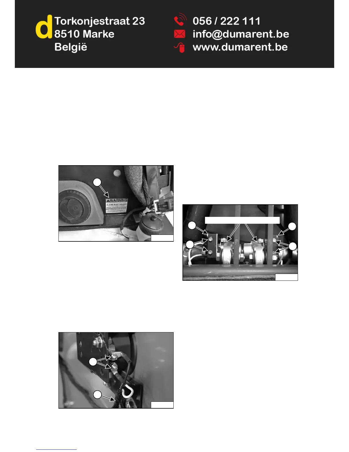
Figure 157
Inspect for damaged or missing back-up alarm decal
(Item 1) [Figure 157]. Replace if required.
Sit in the seat and fasten the seat belt. Engage the
parking brake. Pull the seat bar all the way down. Start
the engine. Press the PRESS TO OPERATE LOADER
button. Disengage the parking brake.
Move both steering levers or joystick(s) into the reverse
position. The back-up alarm must sound when all wheels
or both tracks are moving in reverse.
The back-up alarm is located on the inside of the rear
door.
Figure 158
Inspect the back-up alarm electrical connections (Item 1),
wire harness (Item 2) [Figure 158] and back-up alarm
switches (if equipped) (Item 2) [Figure 159] for tightness
and damage. Repair or replace any damaged
components.
If the back-up alarm switches require adjustment, (See
Adjusting Switch Position on Page 119.)
Adjusting Switch Position
NOTE: Joystick equipped machines do not have
back-up alarm switches and cannot be
adjusted. See your Bobcat dealer for service if
your back-up alarm does not sound.
Standard Controls, ACS and AHC (If Equipped)
Stop the engine and raise the operator cab. (See Raising
on Page 120.)
Figure 159
Place the steering levers in the neutral position.
Loosen the screws (Item 1) [Figure 159] securing the
back-up alarm switches.
Position the back-up alarm switch rollers so that they just
make contact with bellcranks without compressing the
switch springs [Figure 159]. Torque the screws (Item 1)
[Figure 159] securing the switches to the bracket to 1,6 -
2,1 N•m (14 - 19 in-lb).
Lower the operator cab. (See Lowering on Page 121.)
Inspect back-up alarm system for proper function. (See
Inspecting on Page 119.)
 Loading...