22
09665-07.2021-Gb
8 I Electromagnetic coupling
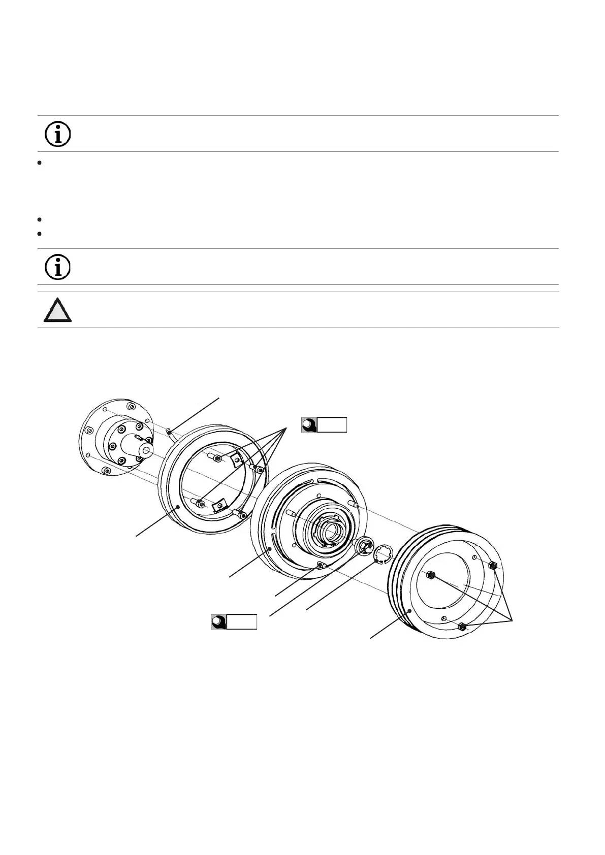
Remove the K-circlip (5) and the clamping screw (4) from the rotor assembly (3). Looking through the rotor hole, pay attention to the cor-
rect seating of the Woodruff key in the rotor slot. It should be possible to turn the rotor by hand without the rotor touching the solenoid.
Pay attention to the checking projection! Screw on the clamping screw (4) and tighten it. Screw tightening torque: 85 Nm. Install the
K-circlip (5).
Push the sheave (6) over the studs (9) and fasten it with zinc-coated M8 DIN 934-8 nuts (7).
Connect the cable (8). The connection is polarity-independent. Voltage ± 10% of nominal voltage.
Fig. 10
ATTENTION With all other methods of removal (pressing, hammering) there is risk of damage to the coupling.
INFO Arrange the cable (8) so that it doesn‘t touch hot parts (e.g. protection pipe).
t
max
= 105°C!
INFO For dismounting the coupling apply grease to the K-circlip and turn the clamping screw (4) to the left
for unscrewing.
85 Nm
Bearing ange
3
1
8
9
2
4
5
6
7
34 Nm