Page 5
A
B
A
#34 Washer (M10)
[8 pieces]
#38 Hex Bolt (M10x35 mm)
[2 pieces]
#25 Hex Bolt (M10x30 mm)
[2 pieces]
#29 Lock Nut (M10)
[4 pieces]
Bolts
Nuts
Washers
Assembly Instructions
A s s e m b l y S t e p 1
Hardware Required
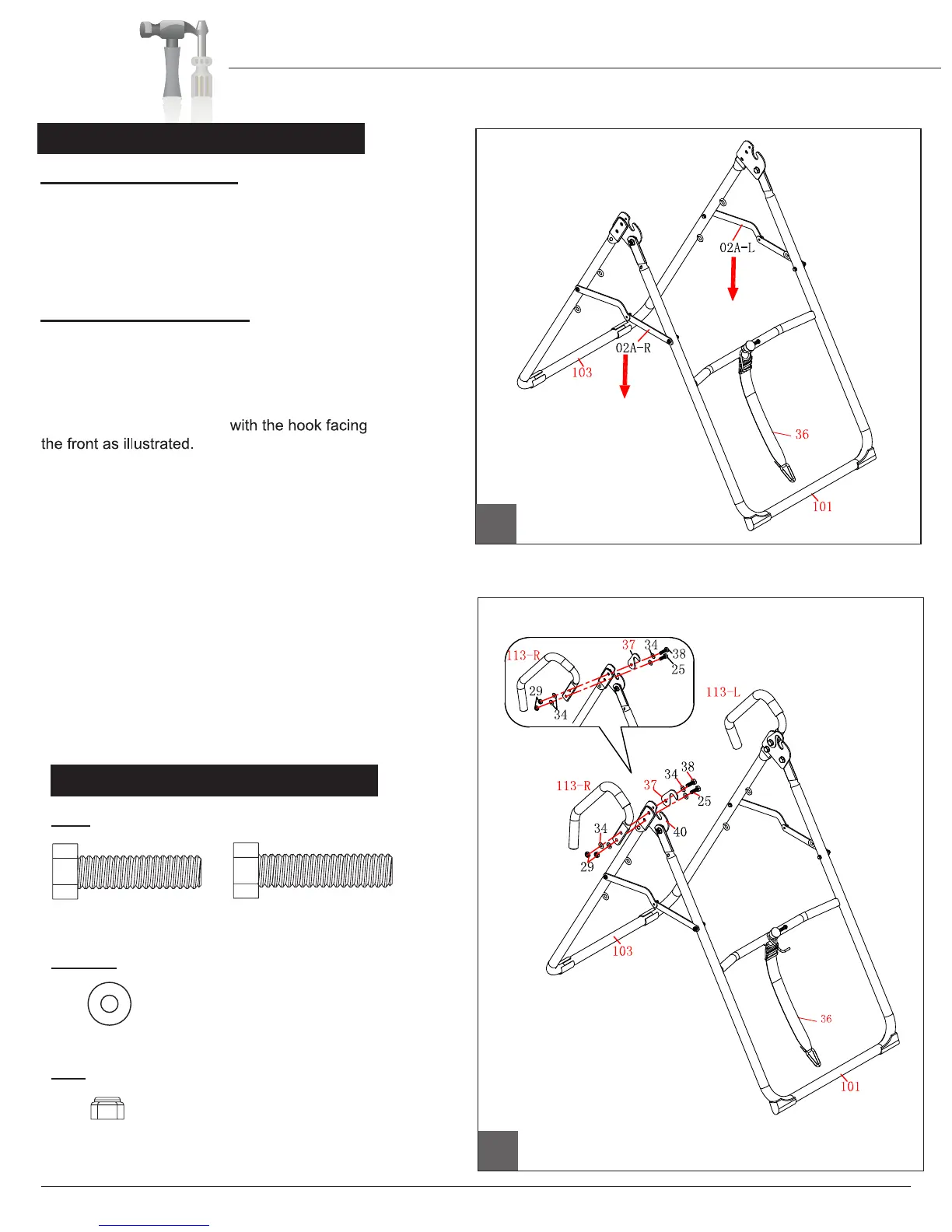
B.) Hand Rail Assembly
Align the top hole located on the Rear Base (#103)
with the middle hole located on the Pivot Bracket
(#40). Position the Right Hand Rail (#113R)
on the outside of the Rear B ase (
#103) and
position one Safety Hook (#37) on the inside
of the Pivot Bracket (#40)
Insert a Hex Bolt
(#38) through a Washer (#34) followed by the
Safety Hook (#37), Pivot Bracket (#40), Rear
Base (#103), Right Hand Rail (#113R), Washer
(#34) and secure it with a Lock Nut (#29).
Align the lower hole located on the Rear Base
(#103) with the lowest hole located on the Pivot
Bracket (#40) and the lower hole located on
the Right Hand Rail (#113R).
Insert a Hex Bolt
(#25) through a Washer (#34) followed by the Pivot
Bracket (#40)
, Rear Base (#103), Right Hand Rail
(#113-R), Washer (#34) and secure it with one Lock
Nut (#29). Repeat this process on the opposite side.
Please look at the diagrams and make sure
you assembled all of the parts as illustrated.
A.) A-Frame Assembly
Open the pre-assembled A-Frame, which is composed
of Front Leg Tube (#101), Rear Base (#103) and left
and right Cross Support Brackets (#02A-L/R). Make
sure that the two Cross Support Brackets (#02A-L/R)
are fully extended and firmly locked in place by pressing
down on them.
IT8020