B737
MAINTENANCE MANUAL
EFFECTIVITY
Post ELT STC ST03081AT
23-24-00
PAGE 203
JAN 02/07
NOTE: If the check out is going to conclude with step (5) below, then reseat the battery pack on
the ELT, dressing the harness wires away from the standoffs to avoid pinching the wires
between the battery pack and the standoffs. Reinstall the four Phillips head screws and
tighten securely. Do not over torque the screws.
(5)
G-switch Check
NOTE: The ELT cannot be activated in this way unless pins 5 and 8 are jumpered (this
happens automatically when the unit is locked into the mounting tray with the connector
in place). Because of the potential physical damage which could occur through an
improper jumper, it is recommended that this step be performed only by an experienced
technician/mechanic. See ARTEX Document 570-5001, “Installation” section for pin
layout diagram. A test plug may be obtained from ARTEX (P/N 151-2012) to use in
performing this test.
(a) While monitoring 121.5 MHz on an AM receiver, and with the unit switch in the OFF
(down) position, activate the ELT by using a rapid forward (throwing) motion, in the
direction of the arrow, followed by a rapid reversing action.
(b)
Verify activation via the aural swept tone on the receiver.
(c) Following activation, “RESET” the unit by toggling the ON/OFF switch to ON then
back to OFF.
(6)
Electrical Check
(a) Activate the ELT. As the unit will be on for three minutes it is recommended that it be
placed in a container capable of substantially attenuating RE signals. Remember
that all tests must be performed within the first five minutes after the hour UTC
(Universal Coordinated Time).
(b) Monitor the following performance criteria for three minutes (power output must be
made at the end of the three minute period).
(c) Ensure that adequate attenuation rated for 406.025 MHz, 5 Watts is installed
between the ELT’s 121.5/243/406 MHz output and the input to measurement
equipment to prevent damaging the input circuitry.
(7)
121.5/243/MHz Power Output
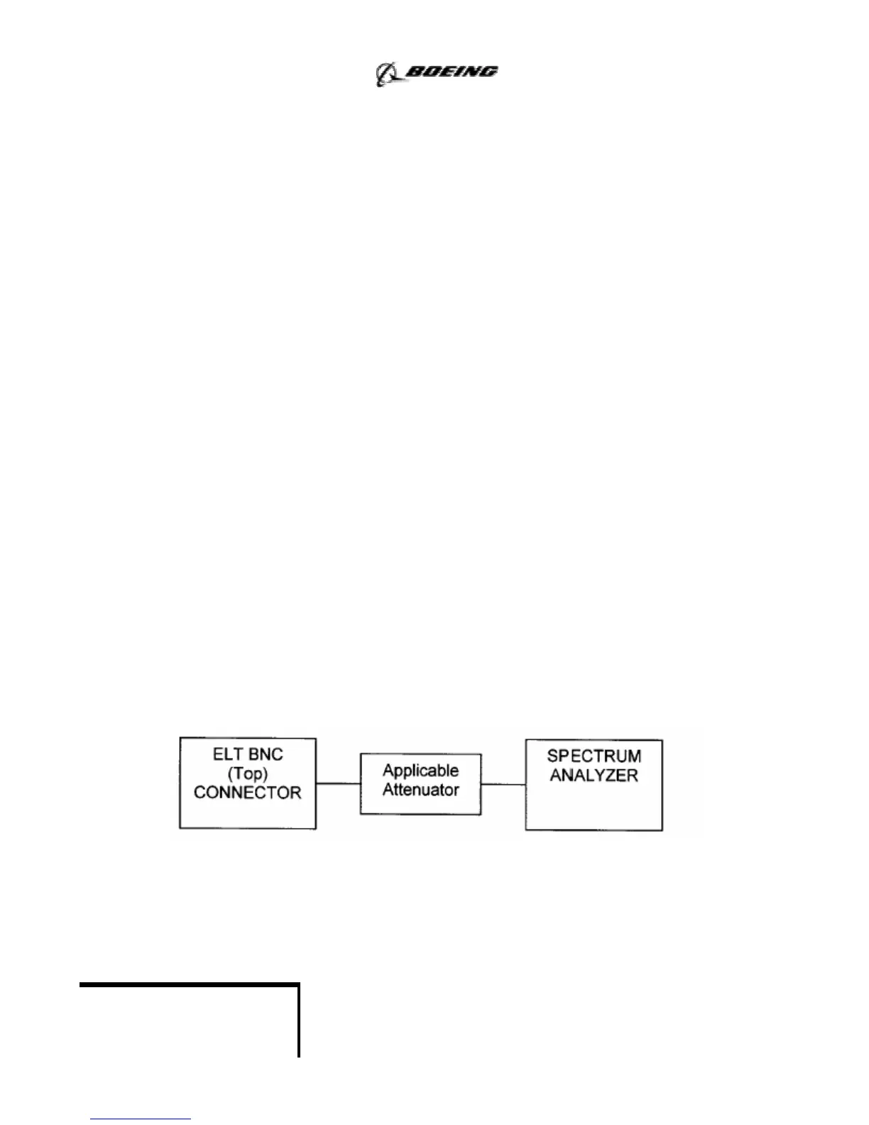
(a)
Connect the equipment as shown below:
NOTE: Use a fresh battery pack (12.5 volts nominal) or a 4 amp, 12.5 vdc power supply as
power source.
NOTE: The test equipment specified in the following steps is only a recommendation. The use
of other manufacture’s models of test equipment capable of providing equivalent
measurements results is acceptable.