Do you have a question about the Bombardier-Rotax ROTAX FLYDAT and is the answer not in the manual?
Details the setup and wiring for liquid-cooled 2-stroke engines.
Details the setup and wiring for air-cooled 2-stroke engines.
Details the setup and wiring for liquid-cooled 4-stroke engines.
Explains PC connection for programming and data transfer via RS-232.
Describes connecting external signaling devices and push buttons.
Lists general operational parameters like power supply, temperature, and weight.
Details the types of sensors supported and their measuring ranges.
Specifies warning and alarm limits for engine types 447 and 503UL.
Specifies warning and alarm limits for the 582 UL DCDI engine.
Specifies warning and alarm limits for the 618 UL engine.
Specifies warning and alarm limits for the 912 UL DCDI engine.
Specifies warning and alarm limits for the 912 ULS DCDI engine.
Specifies warning and alarm limits for the 914 UL DCDI engine.
Key factors to consider for safe and reliable FLYdat installation.
Provides physical dimensions for planning the installation location.
Details the components included in the sensor kit for LC 2-stroke engines.
Details the components included in the sensor kit for AC 2-stroke engines.
Details the components included in the sensor kit for 912, 912S, and 914 engines.
Guidelines for routing sensor lines to prevent damage and ensure accuracy.
Instructions on soldering, insulating, and extending sensor connections.
Specifies torque values and tightening methods for sensor installation.
Illustrates sensor placement for liquid-cooled 2-stroke engines.
Illustrates sensor placement for air-cooled 2-stroke engines.
Illustrates sensor placement for liquid-cooled 4-stroke engines.
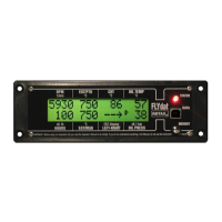
Describes the system's autotest and initial display sequence upon power-up.
Explains the function and states of the instrument's control lamp.
Details how engine speed is displayed, including range and resolution.
Explains the display format and limitations for operating hours.
Describes how temperatures are displayed in °C or °F, including resolution.
Details the display of oil pressure for specific engine types.
Defines the normal operating status where readings are within limits.
Describes the status when warning limits are exceeded, indicated by flashing.
Describes the status when alarm limits are exceeded, indicated by flashing.
Explains how the FLYdat stores and signals data recording events.
Describes the software and process for downloading data from the FLYdat.
Guides the user through the process of updating the FLYdat's firmware.
Explains the iFamily bus connectivity and its capabilities with other instruments.
Covers specific warning messages like "COLD ENGINE" and "OUT OF RANGE".
Details how sensor disconnections are reported (e.g., "---", "Err").
Explains the initial check of internal memories and error reporting.
| Manufacturer | Bombardier-Rotax |
|---|---|
| Model | ROTAX FLYDAT |
| Category | Control Systems |
| Application | Aircraft engine monitoring |
| Type | Engine Monitoring System |
| Operating Temperature Range | -20°C to +70°C |
| Engine Monitoring System | Yes |
| Interface | RS-232 |