22mm
3mm
2
Plastic tube(3x850mm)
3mm
145mm
10mm
10mm
5mm
Metal arms
Ball joint
Pin
Fiberglass pushrod
10mm
1mm
Copper joiner
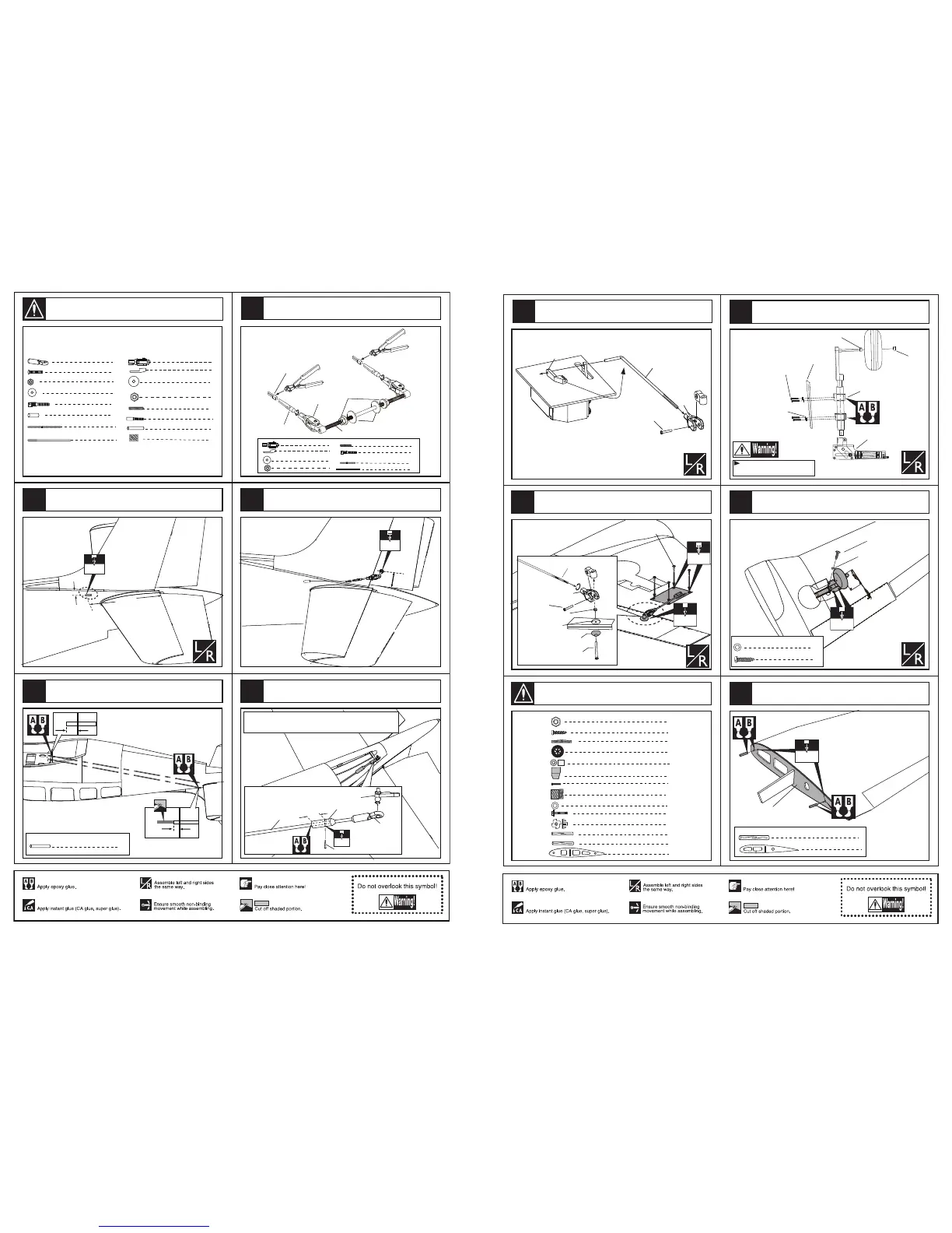
Epoxy the fiberglass pushrod to relevant
position in the fuselage.
Fiberglass pushrod(3x895mm)
1
4
Copper joiner
2
Plastic tube(3x850mm)
4
Ply(20x16x2mm)
2
4
Copper joiner
Aluminum tube(3x6mm)
2
Steel wire (0.5x1500mm)
4
2
2
2
Clevis
Retainer
Washer(3x15mm)
Lock Nut (3mm )
1
Screw (3x80mm)
2
Clevis
2
Screw (2x10mm)
2
Nut (2mm )
2
Washer(2x5mm)
Washer(3x15mm)
Screw (3x80mm)
Lock Nut (3mm )
Clevis
Aluminum tube
Steel wire
2
Steel wire (0.5x1200mm)
1
3
2
2
Clevis
Retainer
Washer(3x15mm)
Lock Nut (3mm )
1
Screw (3x80mm)
2
Copper joiner
Rod (2X300mm)
1
The sketch map after the rudder shaft assemble finished.
Assemble the plastic tubes through the holes in the frame,epoxy
them and Cut off the surplus parts as show in the illustration.
Drill a hole to appropriate position in the rudder
and assemble the rudder shaft.
Epoxy the fiberglass pushrod to the copper joiner tightly.
Customer can drill a hole to the copper joiner and fix a pin
in it for stopping the pushrod from pulling out.
49
50
52
53
10
51
Accessory list for the coming installation steps.
1.5mm
3mm
TP Screw (2.3x12mm)
Note:rubber wheels oleo struts
and retracts are optional.
Retracts strut
Screw (3x10mm)
Gear door
Washer(3x6mm)
Main wing joiner
1
1
2
Gear door
2
Wheel (90mm)
8
TP Screw (2.6x14mm)
Washer(3x6mm)
2
2
Wood dowel (6x50mm)
2
Wood dowel (6x30mm)
2
2
Blind Nut (6mm)
Screw (6x50mm)
Screw (3x10mm)
8
8
LockNut (4mm)
LockNut (4mm)
4
Wooden Block(25x15x13mm)
Wooden Block
Clevis
Retainer
Rod (2x300mm)
Rod (2x300mm)
Clevis
Washer(3x15mm)
Washer
Lock Nut (3mm )
Screw (3x35mm)
Screw (2x10mm)
Screw (2x10mm)
2
Bushing (8X6mm)
Bushing (8X6mm)
8
TP Screw (2.6x14mm)
TP Screw (2.6x14mm)
1.5mm
Secure the air retracts gear with typer screw.
Washer(3x6mm)
Washer(3x6mm)
8
6mm
2
Wood dowel (6x30mm)
1
Rib template (2mm ply)
Rib template (2mm ply)
Rib template (2mm ply)
According to the rib template drill holes in one wing and
epoxy wood dowel in them.
Secure the flap servo. Install the nylon control
horn and connect the linkage.
Assemble the wheel and the gear door to the retract.
Install the nylon control horn and connect the linkage.
12
13
11
15
3
Accessory list for the coming installation steps.
14
 Loading...