4
1. The TRM9HC unit should be located on a firm level surface capable of holding the
weight, as close to the dispense point as possible, and orientated so that the on/off
switch and Eliwell control are accessible. Ensure at least 100mm of space is left all-
round the unit to allow adequate airflow for cooling.
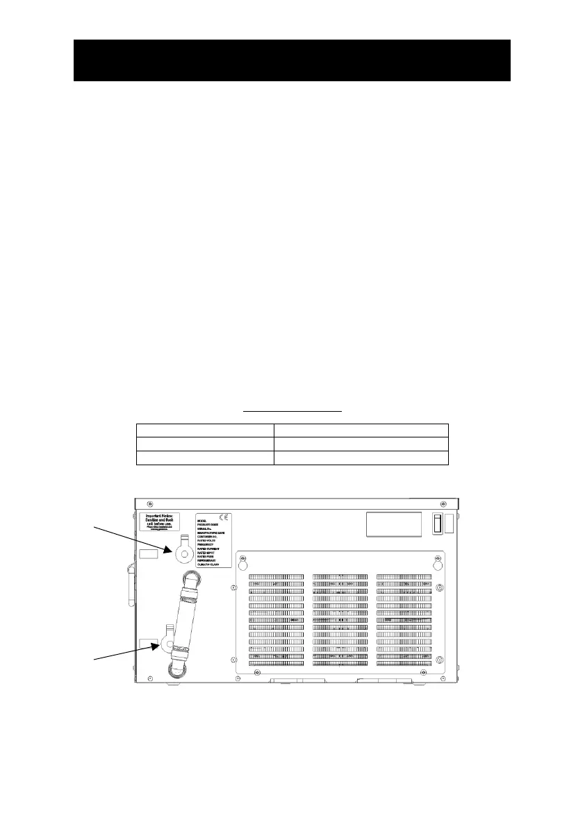
2. Connect using John Guest fittings to “Product In” on the front of the cooler.
3. Connect using John Guest fittings to “Product Out” on the front of the cooler and feed
the insulated product line to the dispense tap.
Note: At this stage do not connect the unit to the electrical supply.
4. Connect the chiller to the water supply and open the mains supply isolation valve.
5. Activate the still water dispense until all air has been purged from the system.
6. Once all air has been purged from the system, connect the unit to the electrical supply
and turn on. After a short delay the compressor and fans will start.
7. After approximately 10 minutes, the compressor and fan will stop as the chiller has
reached its normal operating temperature. Note: The time taken for the chiller to
reach operating temperature will vary depending on ambient temperature,
humidity and the temperature of the incoming water supply.
8. Maintenance: Wipe occasionally with damp cloth.
9. If compressor or thermostat problems occur the control will shut the compressor off
and display an error code. This should be quoted when requesting assistance.
Product Connections