EasyManua.ls Logo

Bosch Rexroth AG VT 3000 User Manual

Bosch Rexroth AG VT 3000
8 pages
To Next Page IconTo Next Page
Page #1 background imageLoading...
Page #1 background image
1/8
Analog amplifier
Type VT 3000
Component series 3X
RE 29935/10.12
Replaces: 11.06
Overview of contents Features
Suitable for the control of pilot operated proportional direc-
tional valves (type .WRZ, up to component series 6X) and
direct operated proportional pressure valves (type DBEP6
and 3DREP6, each component series 1X) without electrical
position feedback
Four command values adjustable with potentiometers
Four command value call-ups with LED display
Differential input
Step function generator
Ramp generator
Two pulsed current output stages
Polarity protection for the voltage supply
Note:
When supplied the amplifiers have a ramp time of 5 s (setting
of the ramp time of 1 s see page 6).
Contents Page
Features 1
Ordering code 2
Functional description 2
Block circuit diagram / pin allocation 4
Technical data 5
Output curve 6
Indicator / Adjustment elements 6
Unit dimensions 7
Engineering notes / maintenance instructions /
supplementary information 7
H4162
similar figure
Question and Answer IconNeed help?

Do you have a question about the Bosch Rexroth AG VT 3000 and is the answer not in the manual?

Bosch Rexroth AG VT 3000 Specifications

General IconGeneral
BrandBosch Rexroth AG
ModelVT 3000
CategoryAmplifier
LanguageEnglish

Summary

Analog Amplifier Overview

Product Features

Key functionalities and capabilities of the VT 3000 analog amplifier.

Ordering Code

Functional Description

Command Value Inputs and Potentiometers

Details on how command value inputs, relays, and potentiometers are used for signal control.

Ramp and Step Function Generators

Explanation of ramp and step function generators for signal shaping.

Output Stages and Status Indicators

Description of output stages, LEDs for status indication, and fault handling.

Block Circuit Diagram and Pin Allocation

Technical Data

Output Curve and Indicators

Output Current Curve

Graphical representation of output current versus command value for solenoids.

Indicator and Adjustment Elements

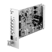
Layout of LEDs, potentiometers, and measuring sockets on the amplifier card.

Unit Dimensions and Installation Notes

Unit Dimensions

Physical dimensions of the analog amplifier card in millimeters.

Engineering and Maintenance Notes

Important notes for installation, maintenance, and operation.