20 | English
1 609 929 W88 | (1.6.10) Bosch Power Tools
f Keep your workplace clean. Blends of mate-
rials are particularly dangerous. Dust from
light alloys can burn or explode.
f Always wait until the machine has come to
a complete stop before placing it down. The
tool insert can jam and lead to loss of control
over the power tool.
f Never use the machine with a damaged ca-
ble. Do not touch the damaged cable and
pull the mains plug when the cable is dam-
aged while working. Damaged cables in-
crease the risk of an electric shock.
f Products sold in GB only: Your product is fit-
ted with an BS 1363/A approved electric plug
with internal fuse (ASTA approved to
BS 1362).
If the plug is not suitable for your socket out-
lets, it should be cut off and an appropriate
plug fitted in its place by an authorised cus-
tomer service agent. The replacement plug
should have the same fuse rating as the origi-
nal plug.
The severed plug must be disposed of to
avoid a possible shock hazard and should nev-
er be inserted into a mains socket elsewhere.
Products sold in AUS and NZ only: Use a re-
sidual current device (RCD) with a rated re-
sidual current of 30 mA or less.
Functional Description
Read all safety warnings and all in-
structions. Failure to follow the
warnings and instructions may re-
sult in electric shock, fire and/or se-
rious injury.
While reading the operating instructions, unfold
the graphics page for the machine and leave it
open.
Intended Use
The machine is intended for making separating
cuts and cut-outs in wood, plastic, metal, ce-
ramic plates and rubber while resting firmly on
the workpiece. It is suitable for straight and
curved cuts with mitre angles to 45°. The saw
blade recommendations are to be observed.
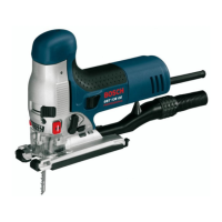
Product Features
The numbering of the product features refers to
the illustration of the machine on the graphics
page.
1 Plastic cap
2 Lock-on button for On/Off switch
(GST 135 BCE)
3 On/Off switch
4 Thumbwheel for stroke rate preselection
5 Vacuum connection*
6 Sliding shoe*
7 Base plate
8 Switch for sawdust blowing device
9 Adjusting lever for orbital action
10 Precision-Control button
11 Precision-Control guide cheeks
12 Guide roller
13 Saw blade*
14 Contact protector
15 Stroke rod
16 Dust cover for vacuuming*
17 SDS clamping lever for saw blade release
18 Handle (insulated gripping surface)
19 Vacuum hose*
20 Extraction adapter*
21 Splinter guard*
22 Scale for mitre angle
23 Thumbwheel for pre-tension of base plate
24 Base plate clamping lever
25 Lead for the parallel guide
26 Locking screw for parallel guide*
27 Parallel guide with circle cutter*
28 Centring tip of the parallel guide*
*Accessories shown or described are not part of the
standard delivery scope of the product. A complete
overview of accessories can be found in our acces-
sories program.
OBJ_BUCH-796-004.book Page 20 Tuesday, June 1, 2010 11:23 AM