-8-
Operating Instructions
Assembly
Disconnect the plug from
the power source before
making any assembly, adjustments or
changing accessories. Such preventive
safety measures reduce the risk of starting
the tool accidentally.
BLADE INSTALLATION
The 1575A will cut foam rubber, urethane
foam and other synthetic foams. Its cutting
capacity depends on the length of blades and
guide used.
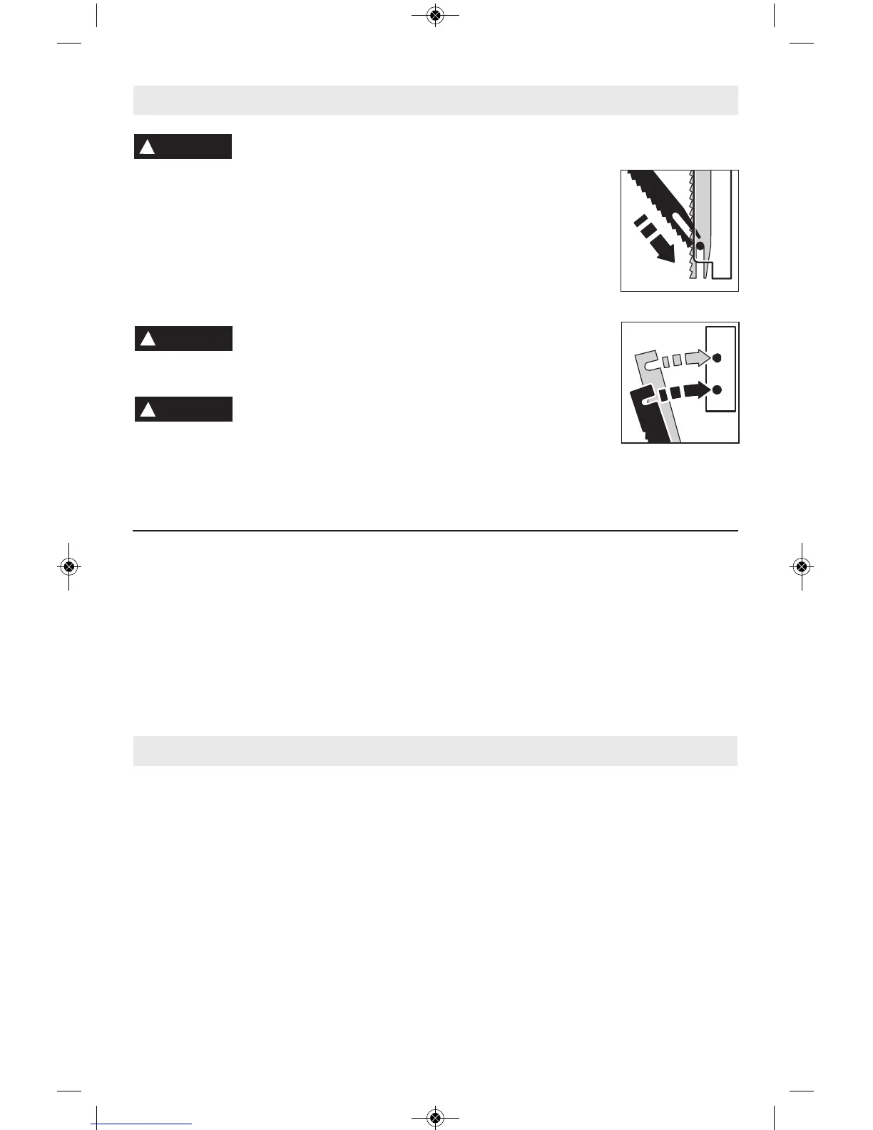
The foam cutter blades are
sharp and susceptible to
bending and must be handled carefully to
avoid injury to user or bending of the blades.
In order to avoid accidents,
always match the blade and
blade guide length to the material to be cut.
Never expose any excessive blade length
above or below the material.
INSTALLING AND CHANGING
THE BLADES:
Remove screws (A),
knurled nuts, lockwashers
and face plate from the
tool. Install the blade guide
with the slot towards the
front of the tool, being sure
to align the locating pins in
the corresponding holes.
Install screws (A) and securely tighten.
Insert the lightly lubricated
blades into the blades
guide so that the vertical
slots in the bottom of the
blades drop over the pin in
the bottom of the blade
guide. Align the horizontal
slots at the top of the
blades with the drive pins in the bottom of the
gear box and slide the blades in until recessed
slightly. Install face plate, lockwashers, and
securely tighten knurled nuts.
FOOTPLATE INSTALLATION
The 1575A may be used with or without the
foot plate, which facilitates guiding the saw and
enables sharp corners to be cut. The foot plate
may be removed when cutting random shapes.
Installing the footplate: Press the foot plate
into the blades guide. Tighten foot plate onto
blade guide using locking screw (B) (Fig. 1).
PADDLE SWITCH WITH “LOCK-ON”
FEATURE
The Paddle Switch enables the operator to
control the switch functions of “ON/OFF” and
“Lock-ON”.
TO SWITCH TOOL “ON”: Squeeze and hold
the paddle lever.
TO SWITCH TOOL “OFF”: Release pressure
on the paddle lever. The switch is spring
loaded and will return to “OFF” position
automatically.
The “Lock-ON” feature, incorporated into the
paddle switch, is a convenience for long
operations.
TO LOCK SWITCH “ON”: After switch has
been activated, PULL the front portion of the
paddle lever completely BACKWARD and
release pressure on the paddle lever.
TO SWITCH TOOL “OFF”: Squeeze the rear
portion of paddle lever and then release the
paddle lever. The switch is spring loaded and
will return to “OFF” position automatically.
!
WARNING
!
WARNING
!
WARNING