18
Before operating, make sure
the entire unit (table with router
installed) is placed on and secured to a solid, flat,
level surface and will not tip. Use of auxiliary in-feed
and out-feed supports is necessary for long or wide
workpieces. Long workpieces without adequate
support can cause the router table to tip over.
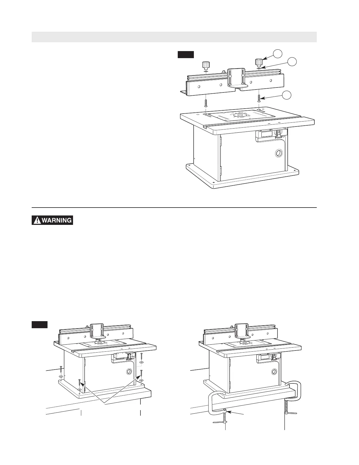
SECURING THE ROUTER TABLE TO A
WORK SURFACE (Fig. 15)
Preferred method:
The base of the router table has four mounting holes.
These holes can be used to attach it to a workbench
or work surface with four 1/4
″ wood screws and
washers or bolts, washers, and nuts (not provided).
1/4
″″
WOOD SCREWS OR BOLTS
C-CLAMPS
FIG. 15
OR
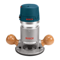
Router Table Assembly
ATTACHING THE FENCE TO THE TABLE
(Fig. 14)
1. From underneath, slide two 1/4-20 x 1
3
⁄4″ carriage
bolts (41) up through the holes in the bottom of the
fence. Slide a large washer (31) onto each bolt and
l
oosely attach a large clamping knob (19) onto
each bolt.
2. Insert the carriage bolt heads through the holes of
the J-slots on the tabletop, making sure the bolt
head is below the inside surface of the tabletop and
can slide freely into the J-slot.
3. Slide the fence assembly left and into the J-slot and
make sure that it slides smoothly from front to back.
NOTE: Use the scale on the tabletop as a guide
when aligning the fence for routing operations. Once
the fence is positioned and aligned correctly, tighten
the clamping knobs SECURELY.
19
FIG. 14
31
HINT: Position the router table in the desired location
and mark the hole locations using the holes in the table
base. Then drill suitable pilot (for wood screws) or
through-holes (for bolts).
Alternative method:
The base can be secured to a workbench or work
surface with C-clamps.
41