Maintenance and service
53
940 ES – 6 720 644 930 (2019/09)
Static Gas Pressure: “ WC
P1 Operating Pressure: “ WC
The P1 minimum operating gas pressure is 3.5" WC for Natural
Gas and 8" WC for Propane. Do not proceed in adjusting CO
2
until pressure is at or above these levels, but not to exceed
10.5" WC for Natural Gas and 13" WC for Propane.
A. Once Gas Pressure is adequate
▶ Press ON/OFF button to turn OFF the heater.
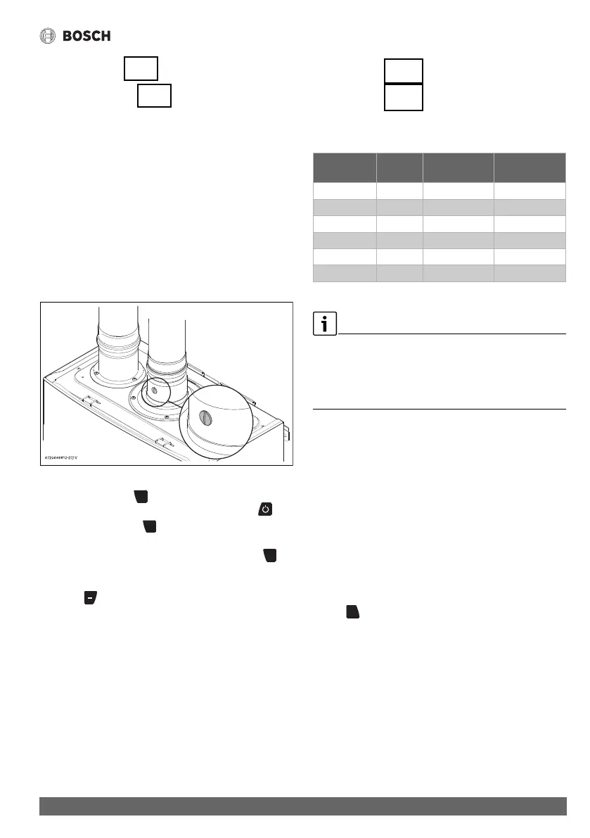
▶ Remove brass flat head screw on the exhaust collar as seen
in fig. 60.
▶ Insert CO
2
analyzer probe into the measuring port. The tip
of the probe should be in the center of the flue pipe (approx
1.5" inserted). Avoid air gaps between probe and
measuring port as they can alter readings.
Fig. 60 Measuring port
▶ Push and hold the button.
▶ Turn power back on by pushing the power button .
▶ Continue to hold the button until all symbols on the
screen light up and the temperature reads 188 °C.
▶ When display reads 188, immediately release the
button.
The display should now read P2.
▶ Press button until “P1” appears on display.
B. Measuring CO
2
(Combustion cover Installed):
▶ Open all hot water taps to achieve a flow rate of at least 6
gallons per minute. (1 tub and 2 sinks should be sufficient).
If heater display reverts back to P2, open more hot water
fixtures to allow sufficient flow. Press + until P1 reappears
on the display.
▶ Record the CO
2
reading in P1 below. (Analyzer reading may
take several minutes to stabilize).
▶ Press the ‘+’ button until P2 appears. Unit will ramp down to
low fire and the water flow should decrease.
▶ Record the CO
2
reading in P2 below.
P1 CO
2
Reading: % CO
2
P2 CO
2
Reading: % CO
2
Note: When making adjustments, make sure combustion cover
is installed.
Table 36 CO2 & CO target numbers
Values above are for climate controlled conditions. Inputs such
as gas pressure, heating value of the gas, humidity and
temperature of combustion air all impact CO and CO2 values.
Changes in these inputs can result in different CO and CO2
values on the same appliance.
C. Adjusting CO
2
:
Note: P1 adjustment will change the P2 reading. Confirm
the P1 value BEFORE adjusting the P2 level.
1. If P1 CO
2
level is off:
▶ Loosen yellow painted Phillips screw (1) and cover should
rotate down (2) revealing a recessed brass slotted screw.
Fig. 61.
▶ Turning the slotted screw counter clockwise will raise P1
CO
2
levels and clockwise will lower P1 CO
2
levels.
Adjustments to the slotted screw will also change P2 CO
2
levels.
▶ After bringing the P1 CO2 readings in proper range, press
the button to enter the P2 mode. Verify CO
2
readings
in P2 mode.
2. If P2 CO
2
level is off:
▶ Remove yellow painted #40 Torx cover from the front of the
gas valve. (Fig. 62) A plastic #40 Torx screw will be
revealed.
▶ Turning the plastic #40 Torx screw counter clockwise will
lower P2 CO
2
levels and clockwise will raise P2 CO
2
levels.
Note: This screw adjustment is very sensitive and should be
made in small increments. It may take several minutes for
readings to stabilize.
CO2 range (%) Max. CO level
(measured)
Nat. Gas
max. input P1 6.3% - 6.9% < 250ppm
min. input P2 2.3% - 2.6% < 60ppm
LP Gas
max. input P1 8.7% - 9.3% < 250ppm
min. input P2 2.7% - 3.0% < 60ppm
+
 Loading...