10
Fig. 7 - Water valve and S bend water connectors - top view
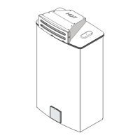
Fig. 6 - Appliance pressure regulator
(with directional arrow on reverse side pointing up)
The pressure regulator provided with the heater is adjusted
to deliver the proper gas pressure (as indicated on the
rating plate and in the manual for altitude up to 2000 feet
(660 meters) above sea level. On appliances being installed
above 2000 ft (660 meters) elevation, the inlet gas pressure
should be set at installation to the value shown below.
NOTE: The gas pressures specified below refer to
pressures taken at the test pressure nipple on the gas
inlet pipe just above the regulator (See Fig 6). These
readings should be taken while the heater is operating
at full input i.e. maximum water flow with the
temperature dial selector turned all the way
clockwise.
MAXIMUM INLET PRESSURE SETTINGS
Above 4.500 ft consult your local gas provider.
It is strongly recommended that the natural gas pipe line
be 3/4" for the entire distance. If the maximum length is
above 40 feet, use 1" line. Flexible tubing is NOT
recommended, but if it is to be used, oversize it. With LP
gas installation, the recommended sizes are 5/8" up to a
maximum of 20 feet distance, 3/4" up to 50 ft distance and
7/8" up to 100 feet.
National Fuel Gas Code requires that a sediment trap (drip
leg) be installed on gas appliances. The drip leg must be
accessible and not subject to freezing conditions. Install in
accordance with the recommendations of the gas supplier.
NOTE: The AquaStar 125FX is supplied with a gas
pressure regulator that must be installed on the heater
before attaching the gas supply line. See figure 6.
Failure to install the gas regulator as shown in figure
6 will be a violation of CSA certification of the unit.
The regulator supplied with the heater is preset for
the gas shown on the rating plate to the correct
pressure. It is an appliance level regulator designed
for (low inlet) pressure (less than 1/2 Psig or 15 W.C.)
DO NOT connect to an unregulated or high pressure
propane line or to a high pressure commercial natural
gas line.
WARNING: The heater must be disconnected from
the gas supply piping system during any pressure testing
of that system at test pressures in excess of .5 psig.
The water heater must be isolated from the gas supply
piping system by closing the manual shutoff valve during
any pressure testing of the gas supply piping system at
test pressures equal to or greater than .5 psig.
The water heater, including the pressure regulator provided
with it, must not be operated at gas supply pressures in
excess of .5 psig. If overpressure has occurred, such as
through improper testing of the gas lines or malfunction of
the supply system, the gas valve and regulator must be
checked for safe operation.
When your connections are made, check for gas leaks at
all joints (not just the ones you made). Apply some soapy
water to all gas fittings and gas valve. Soap bubbles are
a sign of a leak.
NOTE: Do not apply soap solution to pilot filter screen or
pilot orifice area. If you have a leak, shut off the gas. After
verifying that required gaskets are in place, tighten
appropriate fittings to stop leak. Turn the gas on and check
again with a soapy solution. Never test for gas leaks using
a match or flame.
WATER CONNECTIONS
When facing the heater, the cold water inlet is on your right
and the hot water outlet is on your left.
Although water piping throughout your structure may be
other than copper, CEC recommends that copper piping
be used for at least three feet before and after the heater
(follow local codes if more stringent). Keep water inlet pipe
to no less than 1/2 inch diameter to allow the full flow
capacity. Remember that water pressure must be sufficient
to activate the heater when drawing hot water from the top
floor. If the hot and cold connections to the heater are
reversed, the heater will not function. The AquaStar 125FX
is provided with two S-bend water connection adapters that
must be connected to the inlet and outlet fittings of the
water valve as shown in Figs 7 and 8. Galvanized or brass
90 degree elbows work best when connected to the S
fittings. These fittings seal to the water valve by means of a
union connection with a washer type gasket at the joint.
No pipe dope or thread tape is to be used at these joints.
The Pressure Relief Valve (PRV) should only be fitted to
the hot water line. Be certain there are no loose particles
or dirt in the piping. Blow out or flush the lines before
connecting to the AquaStar. Full port ball valves should be
installed on both the cold water feed line and the hot water
outlet line to facilitate servicing the heater.
For installation on a private well system, be sure that the
minimum water pressure is set between 30 and 50 psi.
Altitude Natural Gas Liquid Propane
inches W.C: inches W.C:
0’ - 2.000 ft 5.38 9.9
2.000 ft - 4.500 ft 4.40 7.90
GAS INLET PIPE
PRESSURE TAP
APPLIANCE PRESSURE
REGULATOR
(with directional arrow on
reverse side pointing upward)
PLASTIC CAP
 Loading...