18 | English
1 609 929 K01 | (1.10.07) Bosch Power Tools
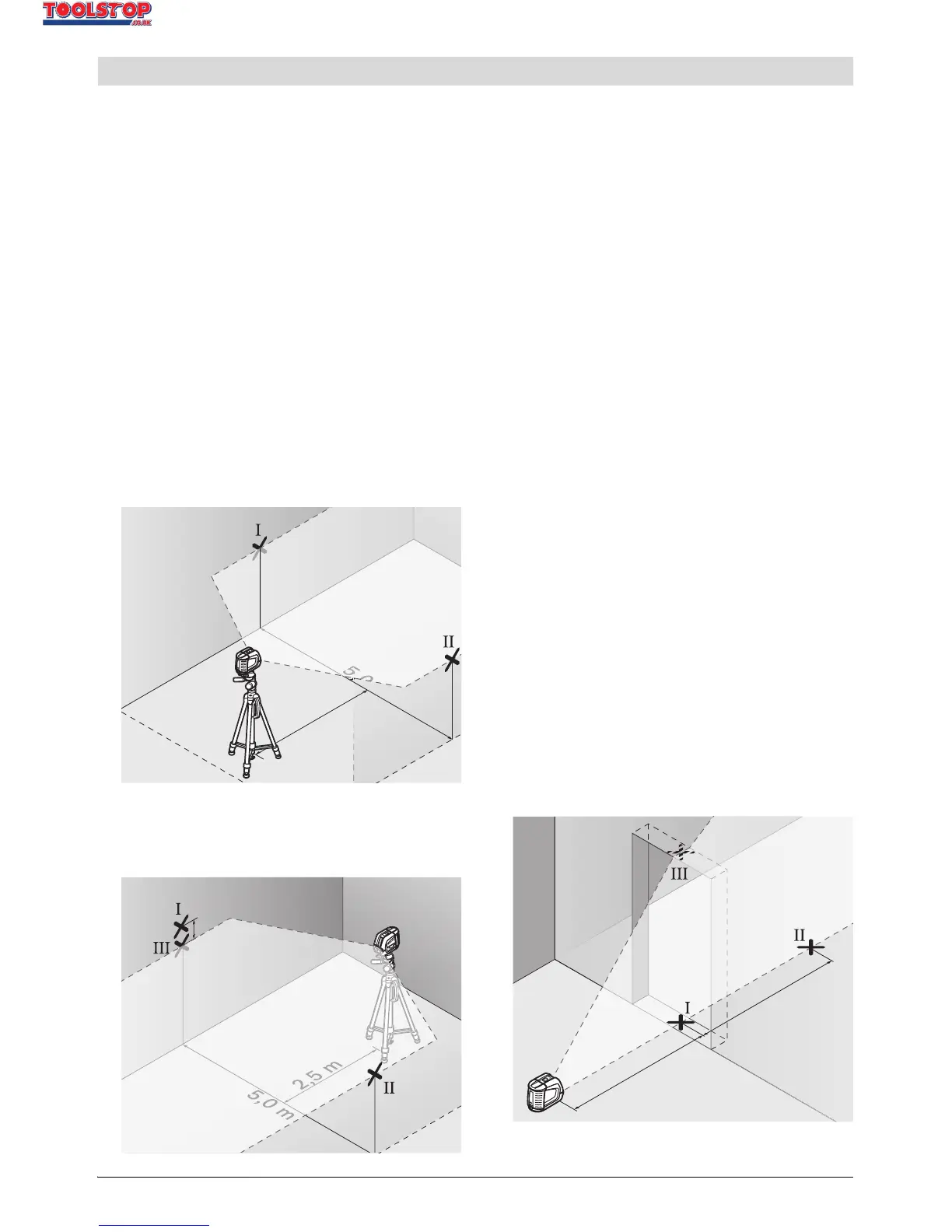
– The difference d of both marked points I and
III on wall A indicates the actual height devi-
ation of the measuring tool.
The maximum permitted deviation d
max
is calcu-
lated as follows:
d
max
= double distance of the walls x 0.3 mm/m
Example: With a 5 metre distance between the
walls, the maximum deviation must not exceed
d
max
=2x5mx0.3mm/m=3mm. Thus, the
marks must not be more than 3 mm apart.
Checking the Levelling Accuracy of the
Horizontal Line
For the check, a free surface of approx. 5 x 5 me-
tres is required.
– Set up the measuring tool on a firm, level sur-
face between both walls A and B. Allow the
measuring tool to level in while in horizontal
operation.
– At a distance of 2.5 metres from the measur-
ing tool, mark the centre of the laser line
(point I on wall A and point II on wall B) on
both walls.
– Set up the measuring tool 5 metres away
turned by 180° and allow it to level in.
– Align the height of the measuring tool (using
a tripod or by underlaying, if required) in
such a manner that the centre of the laser
line is projected exactly against the previous-
ly marked point II on wall B.
– Mark the centre of the laser line as point III
(vertically above or below point I) on the wall
A.
– The difference d of both marked points I and
III on wall A indicates the actual deviation of
the measuring tool from the level plane.
The maximum permitted deviation d
max
is calcu-
lated as follows:
d
max
= double distance of the walls x 0.3 mm/m
Example: With a 5 metre distance between the
walls, the maximum deviation must not exceed
d
max
= 2 x 5 m x 0.3 mm/m = 3 mm. Thus, the
marks must not be more than 3 mm apart.
Checking the Levelling Accuracy of the
Vertical Line
For this check, a door opening is required with
at least 2.5 metres of space (on a firm surface)
to each side of the door.
– Position the measuring tool at a distance of
2.5 metres away from the door opening on a
firm surface (not on a tripod). Allow the
measuring tool to level in while in cross-line
operation and direct the laser beam against
the door opening.
2,5 m



 To Next Page