Service Notes:
Use 1 981 000 975 Spanner Wrench for removal/installation of 1 615 500 214 (Pos. 6) Retaining Nut.
68 1 613 465 001 Handle Bumper {2} 9
69 1 615 700 042 Intermediate Plate 38
70 1 615 132 011 Handle 74
71 1 611 11A 004 Name Plate 9
73 1 603 435 019 Screw {2} 89
74 2 916 160 009 Spring Washer {3} 74
75 3 614 640 501 Spring {3} 27
76 3 611 034 500 Cord Clamp 89
84 1 611 099 003 Mounting Plate 9
85 1 614 336 045 Brush Holder 25
w/pos. 96, 879 - 883
86 1 610 300 033 Pin 54
87 1 610 900 027 Ball Bearing 56
88 1 610 283 016 Oil Seal 77
89 1 610 009 008 Insulating Plate 9
94 1 611 015 021 Gasket 79
95 1 614 431 030 Cable 10
96 1 614 448 037 Cable {2} 10
97 2 915 011 007 Nut {2} 89
99 3 613 313 500 Nut {2} 89
102 2 910 211 025 Screw {2} 89
104 2 910 141 201 Screw {4} 89
105 2 914 551 188 Screw {4} 89
106 2 914 551 189 Screw {4} 89
107 2 910 141 242 Screw {4} 89
108 2 914 201 707 Screw {4} 89
109 2 910 141 248 Screw {9} 89
110 2 910 141 356 Screw {4} 89
111 3 613 450 500 Hex Bolt {3} 89
112 2 910 211 236 Screw {2} 89
114 2 917 721 034 Pin {2} 89
119 1 601 110 058 Label 9
131 1 601 110 618 Label 9
801 1 617 000 851 Motor Housing Assembly 71
w/pos. 11, 12, 15, 67, 71,
86, 87, 88, 114, 813
803 1 614 011 092 Armature 120V AW
813 1 610 910 035 Needle Bearing 61
843 1 617 000 428 Tool Holder Assembly 84
w/pos. 32
854 3 607 000 509 Switch Housing Assembly 74
w/pos. 108, 112
858 1 610 591 001 Switch Button 9
859 2 910 091 118 Switch Screw {6} 89
861 1 617 000 429 Mounting Plate Assembly 9
879 1 614 652 001 Brush Spring {2} 27
881 1 613 490 005 Screw {2} 89
882 2 916 699 130 Lock Washer {2} 65
883 1 617 000 425 Brush Set 26
895 1 615 430 016 Grease 1000ml 1
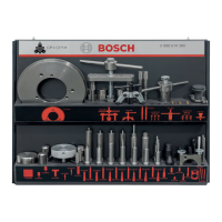
897 1 617 000 426 Service Pack 78
898 1 615 430 015 Grease 225ml 1
2 1 614 220 157 Field 120V 22
4 1 615 805 068 Bearing Housing 73
5 1 610 900 015 Ball Bearing 60
6 1 615 500 214 Retaining Nut 85
7 1 615 108 104 Field Housing 9
8 1 616 610 091 Fan 23
9 1 613 313 000 Nut 89
11 1 610 108 013 Felt Seal 77
12 1 610 102 616 Washer 65
15 1 610 910 091 Needle Bearing 51
19 1 616 110 033 Eccentric Shaft 53
21 1 616 318 009 Eccentric Gear 34
22 1 616 328 036 Intertmediate Gear 31
23 1 610 913 005 Needle Bearing {2} 56
24 1 615 500 323 Gear Housing Cover 70
25 1 612 001 027 Connecting Rod 57
26 1 610 910 092 Needle Bearing 56
27 1 610 210 033 O-Ring {2} 78
28 1 618 700 043 Piston 47
30 1 614 601 039 Retainer 89
32 1 900 210 156 O-Ring {2} 78
33 3 613 101 500 Wrist Pin 47
34 1 618 710 039 Striker 44
36 1 900 210 166 O-Ring 78
37 1 615 806 029 Guide Tube 43
38 1 610 220 009 Ring 49
39 1 614 619 005 Spring 49
40 1 615 700 017 Flange 38
41 1 610 210 008 O-Ring {2} 86
42 1 613 123 003 Impact Bolt 45
44 1 618 045 018 Locking Lever 86
45 1 613 103 004 Locking Bolt 86
46 2 917 760 187 Roll Pin {2} 86
47 1 900 210 172 O-Ring 78
48 1 610 516 007 Eccentric Cover 9
49 1 610 707 000 Sleeve 9
50 3 600 421 500 Brass Bushing 82
51 1 610 703 019 Strain Relief 11
52 1 615 500 324 Slide Housing Cover 70
53 1 615 500 325 Top Housing Cover 70
55 3 604 460 507 Cord 115V 11
55/1 1 900 452 003 Terminal Sleeve {2} 11
56 1 610 703 011 Strain Relief 11
57 1 615 500 212 Switch Cover 9
58 1 617 200 015 Switch 15
59 1 615 700 041 Intermediate Plate 38
60 1 615 500 211 Switch Flange 9
62 1 612 026 011 Switch Lever 63
63 1 615 132 010 Switch Handle 74
64 1 616 334 000 Handle Buffer {2} 9
65 1 613 060 005 Shaft 54
67 2 916 660 023 Retaining Ring 89
Pos. Part Number Description {Qty.} F/C Pos. Part Number Description {Qty.} F/C
+ = Not Illustrated * = As Required F/C = Failure Code AW = Refer to AW Labor Time Chart
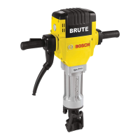
11304 "BRUTE" HAMMER
 Loading...