Battery charger modules Wiring | en 9
Bosch Security Systems, Inc. Installation manual 2018.05 | 4.0 | F.01U.036.305
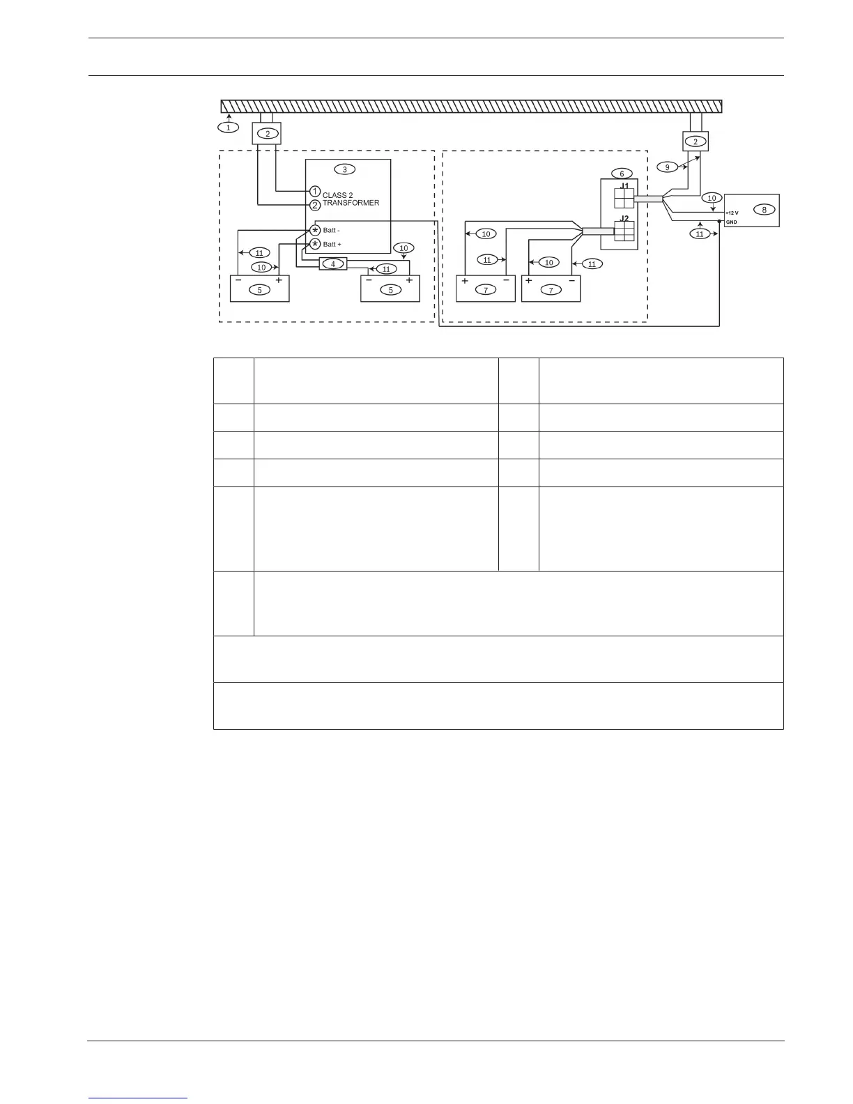
Figure4.3: Wiring D8132 to follow control panel indicators for AC power failure and restoral
1 AC circuit common to both
transformers
2 Transformers*
3 Control panel 4 D122 D battery harness
5 Control panel batteries 6 D8132 module
7** D8132 batteries 8 Devices
9 Gray wires connecting the D8132
module and the D1640 transformer
10 Red wires from positive battery
terminal to the D8132 and the control
panel, and from the D8132 to the
device loop.
11 Black wires from negative battery terminals to the D8132 and the control panel, from
the D8132 to the device loop, and from the device loop ground to the control panel
earth ground.
* GV3 and GV4 panels require a D1640 transformer. For legacy products refer to the control
panel documentation.
** The D8132 can support up to 27 Ah of battery backup. If two batteries are used, they must
have the same Ampere-hour (Ah) rating.
When the control panel and the module are connected to the same AC branch circuit, AC
power failures and restorals which affect the control panel and the module will be indicated
by the control panel. The standalone power supply standby time should be greater than that
of the control panel system. The standalone power supply and the control panel must share a
common ground.
For this type of standalone power supply operation, install the module as shown in the
following figure.