8 en | Wiring Battery charger modules
2018.05 | 4.0 | F.01U.036.305 Installation manual Bosch Security Systems, Inc.
Notice!
The D8132 Module is not UL Listed for “standalone” operation, and cannot be used in this
configuration for UL applications.
To determine the appropriate batteries for use with the module, see the table which displays
auxiliary current and battery recharge values for various battery Ampere-hour combinations in
the section Wiring for extending battery standby time and providing additional auxiliary current
output, page 6. (These values will vary depending upon the condition of the batteries
installed.)
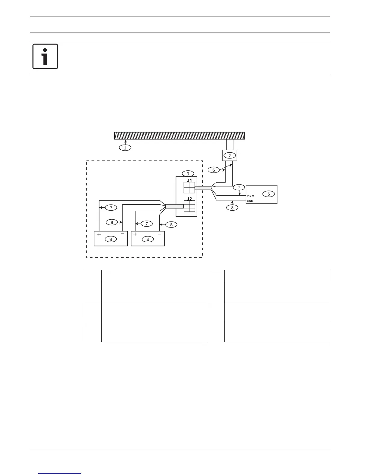
For standalone power supply operation, install the module as shown in the following figure.
Figure4.2: Wiring D8132 as standalone power supply
1 AC branch circuit (unswitched) 5 Devices
2 D1640 transformer 6 Gray wires connecting the D8132
module and the D1640 transformer.
3 D8132 module 7 Red wires from positive battery
terminals to the D8132LT module.
4 Batteries 8 Black wires from negative battery
terminals to the D8132LT module.