Battery charger modules Wiring | en 7
Bosch Security Systems, Inc. Installation manual 2018.05 | 4.0 | F.01U.036.305
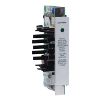
5 Control panel batteries (as needed) 6 D8132 module
7** Additional batteries (as needed) 8 Gray wires connecting the D8132
module and the D1640 transformer
9 Red wires from positive battery
terminals to the D8132 and the control
panel and from the D8132 to the
control panel
10 Black wires from negative battery
terminals to the D81132 and the
control panel and from the D8132 to
the control panel
* GV3 and GV4 panels require a D1640 transformer. For legacy products refer to the control
panel documentation.
** The D8132 can support up to 27Ah of backup battery. If two batteries are used they must
have the same Ampere-hour (Ah) rating.
Two cables are provided with the module for connections to the control panel and additional
batteries.
1. Connect the black wire of the four‑pin connector cable to the control panel’s battery
negative terminal.
2. Connect the red wire of the four‑pin connector cable to the control panel’s battery
positive terminal.
Warning!
Do not short these wires!
3. Plug the four‑pin connector cable into J1 on the module.
4. Connect the two grey wires to a separate 16.5V, 40VA transformer (D1640).
Warning!
Do not connect the grey wires to the control panel’s transformer terminals.
5. Connect the D1640 transformer to an unswitched 110-120VAC 60Hz outlet.
Notice!
Connect the D8132 and the control panel transformers to the same AC branch circuit. Do not
share the transformers with any other devices.
6. Plug the six‑pin connector cable into J2 on the module.
7. Connect a red wire to the positive battery terminal, and a black wire to the negative
battery terminal of each auxiliary battery. (One or two auxiliary batteries can be
installed.)
4.2 Wiring for standalone power supply
The D8132 module can operate as a 12V standalone power supply. Standalone operation
does not have battery supervision or load shed, and therefore is not recommended for critical
loads requiring supervision.