6 en | Wiring Battery charger modules
2018.05 | 4.0 | F.01U.036.305 Installation manual Bosch Security Systems, Inc.
4 Wiring
4.1 Wiring for extending battery standby time and providing
additional auxiliary current output
If the module is to be connected to a control panel to increase stand by time, refer to the
appropriate control panel’s Installation and Operation Guide to calculate the total battery
Ampere-hours (Ah) required for your system. The recharge time cannot exceed 48hours for UL
listed applications. Once satisfactory recharge time, standby time, Ampere-hour, and auxiliary
current values are identified, determine the combination of batteries required for your
application using the following table.
24 standby hours 60 standby hours 72 standby hours Total
battery
Amp-hrs
(Ah)
Aux
current
load
Recharge
time (hrs)
Aux
current
load
Recharge
time (hrs)
Aux
current
load
Recharge
time (hrs)
430mA 9 N/A N/A N/A N/A 12
550mA 10 50mA 7 10mA 7 15
680mA 11 100mA 9 50mA 9 18
800mA 14 150mA 10 90mA 10 21
930mA 17 200mA 12 130mA 12 24
1050mA 21 250mA 14 180mA 13 27
Tab.4.1: Battery requirement
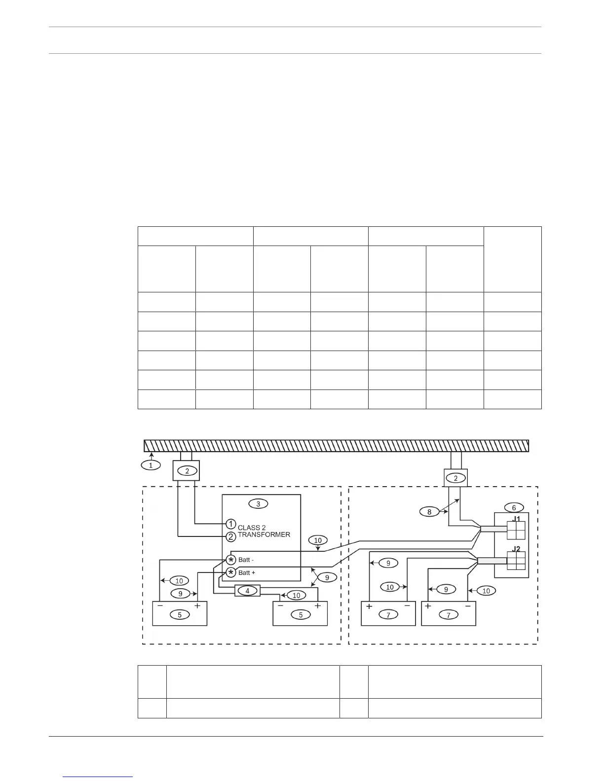
Figure4.1: Wiring for extended battery standby time and providing additional auxiliary current output
1 AC circuit common to both
transformers
2 Transformers*
3 Control panel 4 D122 Dual battery harness