English | 171 609 929 K97 • 25.1.07
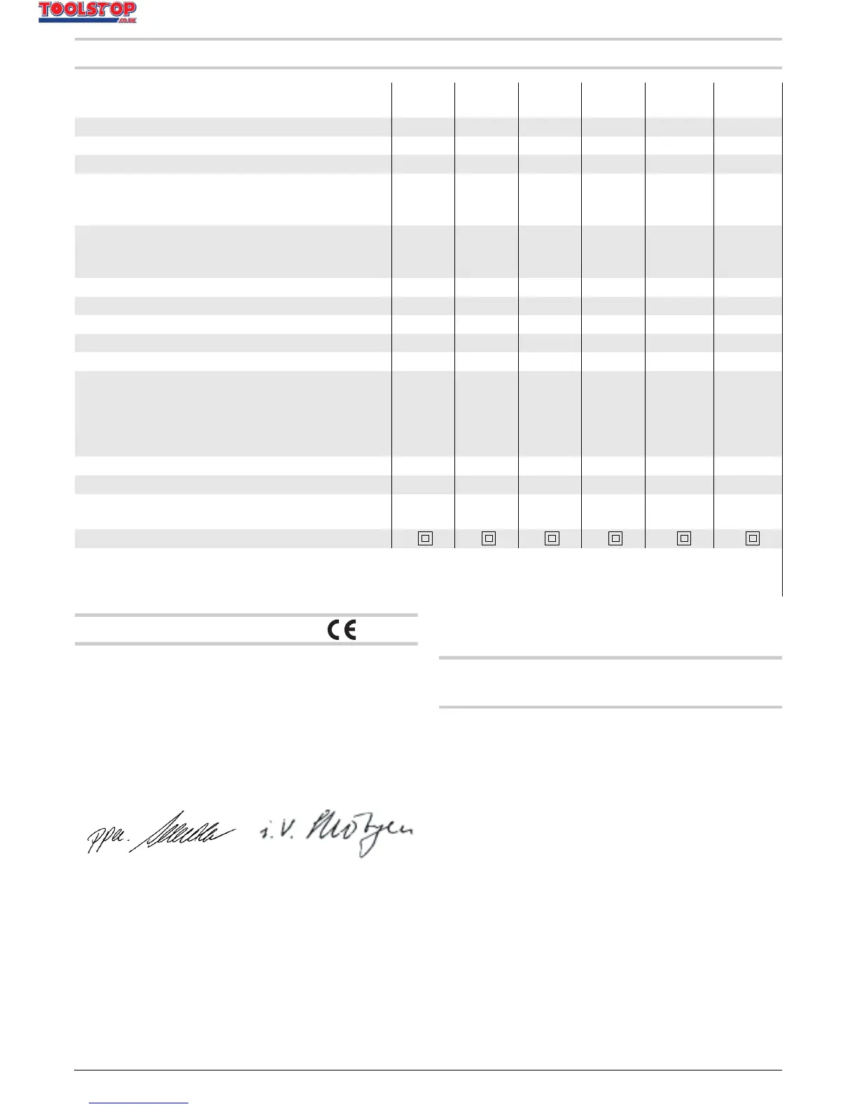
Technical Data
Declaration of Conformity
We declare under our sole responsibility that this prod-
uct is in conformity with the following standards or
standardization documents: EN 60745 according to
the provisions of the directives 89/336/EEC,
98/37/EC.
22.11.2006, Robert Bosch GmbH, Power Tools Division
D-70745 Leinfelden-Echterdingen
Assembly
Auxiliary Handle (GBM 13-2/
GBM 13-2 RE) (see figure A)
f Operate your machine only with the auxiliary
handle 11.
The auxiliary handle 11 can be set to any position for a
secure and low-fatigue working posture.
Turn the wing bolt for adjustment of the auxiliary
handle 10 in anticlockwise direction and set the auxil-
iary handle 11 to the required position. Then tighten the
wing bolt 10 again in clockwise direction.
Adjusting the Drilling Depth
The required drilling depth X can be set with the depth
stop 12.
Loosen the wing bolt for the depth stop adjustment 9
and insert the depth stop rod into the auxiliary handle
11.
The knurled surface of the depth stop 12 must face
upward.
Rotary drill GBM ...
PROFESSIONAL
10 10 RE 10 SRE 10-2 RE 13-2 13-2 RE
Article number 0 601 ... 135 0.. 135 5.. 137 5.. 168 5.. 169 0.. 169 5..
Rated power input W 450 450 420 500 550 550
Output power W 220 220 220 270 285 285
No-load speed
–1st gear
–2nd gear
rpm
rpm
2000
–
0–2200
–
0–2600
–
0–1150
0–2100
1000
1900
0–1000
0–1900
Rated speed
–1st gear
–2nd gear
rpm
rpm
1300
–
0–1300
–
0–1600
–
0–800
0–1500
550
1000
0–550
0–1000
Rated torque (1st/2nd gear) Nm 6.0/– 6.0/– 6.0/– 9.5/5.0 11.5/6.0 11.5/6.0
Spindle collar dia. mm 43 43 43 43 43 43
Speed preselection – – – z – z
Speed control – z z z – z
Right/left rotation – zzz – z
Maximum drilling diameter
(1st/2nd gear)
–Steel
– Wood
– Aluminium
mm
mm
mm
10/–
25/–
13/–
10/–
25/–
13/–
10/–
25/–
13/–
10/6
25/15
13/8
13/8
32/20
20/12
13/8
32/20
20/12
Max. screw dia. mm––6– – –
Chuck clamping range mm 1–10 1–10 1–10 1–10 1–13 1–13
Weight according to
EPTA-Procedure 01/2003 kg 1.5 1.5 1.5 1.7 1.9 1.9
Protection class /II /II /II /II /II /II
The values given are valid for nominal voltages [U] of 230/240 V. For lower voltage and models for specific countries, these val-
ues can vary.
Please observe the article number on the type plate of your machine. The trade names of the individual machines may vary.
Dr. Egbert Schneider
Senior Vice President
Engineering
Dr. Eckerhard Strötgen
Head of Product
Certification
OBJ_BUCH-321-001.book Page 17 Thursday, January 25, 2007 8:36 AM