English | 11
Bosch Power Tools 2 610 017 766 | (5.10.11)
Safety Warnings for Routers
f Hold power tool by insulated gripping surfaces, be-
cause the cutter may contact its own cord. Cutting a
“live” wire may make exposed metal parts of the power tool
“live” and shock the operator.
f Use clamps or another practical way to secure and sup-
port the workpiece to a stable platform. Holding the
work by your hand or against the body leaves it unstable
and may lead to loss of control.
f The allowable speed of the router bit must be at least as
high as the maximum speed listed on the power tool.
Accessories that rotate faster than permitted can be de-
stroyed.
f Router bits or other accessories must fit exactly in the
tool holder (collet) of your machine. Routing bits that do
not fit precisely in the tool holder of the machine rotate ir-
regularly, vibrate heavily and can lead to loss of control.
f Apply the machine to the workpiece only when
switched on. Otherwise there is danger of kickback when
the cutting tool jams in the workpiece.
f Keep your hands away from the routing area and the
router bit. Hold the auxiliary handle or the motor hous-
ing with your second hand. When both hands hold the
machine, they cannot be injured by the router bit.
f Never cut over metal objects, nails or screws. The rout-
er bit can become damaged and lead to increased vibra-
tions.
f Use suitable detectors to determine if utility lines are
hidden in the work area or call the local utility company
for assistance. Contact with electric lines can lead to fire
and electric shock. Damaging a gas line can lead to explo-
sion. Penetrating a water line causes property damage or
may cause an electric shock.
f Do not use blunt or damaged router bits. Blunt or dam-
aged router bits cause increased friction, can become
jammed and lead to imbalance.
f When working with the machine, always hold it firmly
with both hands and provide for a secure stance. The
power tool is guided more secure with both hands.
f Secure the workpiece. A workpiece clamped with clamp-
ing devices or in a vice is held more secure than by hand.
f Always wait until the machine has come to a complete
stop before placing it down. The tool insert can jam and
lead to loss of control over the power tool.
Products sold in GB only: Your product is fitted with an
BS 1363/A approved electric plug with internal fuse (ASTA
approved to BS 1362).
If the plug is not suitable for your socket outlets, it should be
cut off and an appropriate plug fitted in its place by an author-
ised customer service agent. The replacement plug should
have the same fuse rating as the original plug.
The severed plug must be disposed of to avoid a possible
shock hazard and should never be inserted into a mains sock-
et elsewhere.
Products sold in AUS and NZ only: Use a residual current de-
vice (RCD) with a rated residual current of 30 mA or less.
Product Description and Specifica-
tions
Read all safety warnings and all instruc-
tions. Failure to follow the warnings and in-
structions may result in electric shock, fire
and/or serious injury.
Intended Use
The machine is intended for routing grooves, edges, profiles
and elongated holes as well as for copy routing in wood, plas-
tic and light building materials, while resting firmly on the
workpiece.
With reduced speed and with appropriate routing bits, non-
ferrous alloys can also be machined.
Product Features
The numbering of the product features refers to the illustra-
tion of the machine on the graphics page.
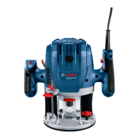
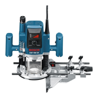
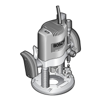
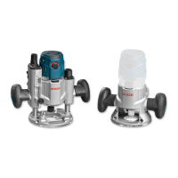
1 Routing motor
2 Plunge base
3 Non-plunge base
4 Handle (insulated gripping surface)
5 Adjustment knob for fine adjustment of depth-of-cut
(plunge base)
6 Scale for depth-of-cut fine adjustment
7 Release lever for plunge action
8 Index mark for fine adjustment
9 Scale for depth-of-cut adjustment (plunge base)
10 Slide with index mark (plunge base)
11 Depth stop (plunge base)
12 Turret stop
13 Base plate
14 Guide plate
15 Thumbwheel for speed preselection
16 Knurled screw for depth stop (plunge base)
17 Tightening nut with collet
18 Router bit*
19 Lock-on button for On/Off switch
20 On/Off switch
21 Securing latch for removal of motor
22 Clamping lever for plunge base/non-plunge base
23 Seat for parallel guide rods
24 Adjustment knob for depth-of-cut fine adjustment (non-
plunge base)
25 Clamping lever for depth-of-cut coarse adjustment (non-
plunge base)
26 Coarse adjustment notches for non-plunge base
27 Spindle lock button
28 Open-end spanner, size 24 mm
29 Knurled screw for extraction adapter(2x)*
30 Extraction adapter (plunge base)*
31 Extraction hose (Ø 35 mm)*
OBJ_BUCH-1559-001.book Page 11 Wednesday, October 5, 2011 7:48 AM
 Loading...