This document provides a quick installation guide for Bosch wall-mounted housings, specifically models HCP 0006 A, HBC 0010 A, and HBE 0012 A. These housings are designed to securely enclose and protect electronic components in various applications.
Function Description:
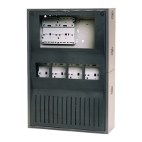
The Bosch wall-mounted housings are robust enclosures intended for the secure installation of internal components. They are designed for fixed wall mounting, providing a protective environment for sensitive electronics. The housings feature pre-cut cable entry points for easy wiring, which, when properly sealed with cable glands, help maintain the specified IP30 conformity. The design allows for organized internal component placement, including provisions for battery installation and connection to power supply units (UPS). The door mechanism is designed for secure closure, indicated by a "closed" and "open" state, likely involving a locking mechanism to prevent unauthorized access. The internal layout includes multiple mounting points and rails for flexible component arrangement.
Important Technical Specifications:
The technical specifications vary slightly between the models, primarily in dimensions and weight, reflecting different capacities.
HCP 0006 A:
- Housing material: Sheet steel, painted. This material choice ensures durability and resistance to environmental factors.
- Housing color: Slate gray RAL 7015 for the main body, with the front in anthracite gray RAL 7016. This provides a professional and discreet appearance.
- Dimensions: Approximately 638 x 440 x 149 mm (height x width x depth).
- Weight: Approximately 12.5 kg.
- Cable entry points: The housing features various pre-cut cable entry points. The larger circular entries have a diameter of 28.4 mm. Smaller rectangular entries are also present.
- Mounting dimensions: The mounting holes are spaced 45 mm from the top edge and 38 mm from the side edges. The overall width for mounting is 350 mm.
- Internal wiring: Specific dimensions for internal wiring, such as 12 mm and 6.5 mm clearances, are indicated, suggesting organized cable routing.
- Grounding: The housing includes a grounding point, essential for electrical safety.
- IP conformity: IP30. This rating indicates protection against solid objects larger than 2.5 mm, but no specific protection against water ingress. Maintaining this conformity requires proper sealing of cable entry points.
HBC 0010 A | HBE 0012 A:
These models share similar material and color specifications with the HCP 0006 A but differ in size and weight.
- Housing material: Sheet steel, painted.
- Housing color: Slate gray RAL 7015 for the main body, with the front in anthracite gray RAL 7016.
- Dimensions: Approximately 840 x 440 x 149 mm (height x width x depth). These models are taller than the HCP 0006 A.
- Weight: Approximately 17 kg.
- Cable entry points: Similar to the HCP 0006 A, with a 28.4 mm diameter for larger circular entries.
- Mounting dimensions: Similar top and side edge clearances (45 mm and 38 mm respectively) and a 350 mm mounting width.
- Internal wiring: Similar internal wiring clearances (12 mm and 6.5 mm).
- Grounding: Includes a grounding point.
- IP conformity: IP30.
Usage Features:
- Wall Mounting: The housings are designed for secure wall mounting, providing a stable and space-saving installation. The installation process involves drilling holes in the wall, inserting wall plugs (S8, Ø8 x 40 mm), and securing the housing with screws (PZ3, Ø6 x 50 mm). Different screw lengths (50 mm for brick/concrete, 4.5 mm for wood) are specified depending on the wall material.
- Cable Management: Pre-cut cable entry points simplify wiring. Users are advised to use cable glands to maintain IP30 conformity when breaking out these points. Internal routing paths and clearances are provided for organized cable management.
- Component Integration: The internal structure is designed to accommodate various components, including CPB 1002 A (likely a control panel board), UPS (Uninterruptible Power Supply) units like UPS 2416 A, and BCM (Battery Control Module) units.
- Battery Installation: The guide illustrates the process of installing batteries, including connecting them to the UPS and BCM. Specific instructions for connecting battery cables (red for positive, blue for negative) are provided, with a clear warning against incorrect connections. The battery cables are shown to be routed through designated openings.
- Access and Security: The door mechanism allows for easy access to internal components for installation and maintenance, while also providing a secure closure. The "closed" and "open" indicators suggest a locking mechanism.
- Tool Requirements: The installation requires standard tools such as a drill (Ø8 mm drill bit), a screwdriver (0.6 x 3.5 mm), and a PZ3 screwdriver.
Maintenance Features:
- Safety Warning: A critical safety warning is provided regarding the risk of electric shock. Users are explicitly instructed to disconnect the device from the power source before any installation or maintenance work to prevent death or serious injury from contact with live parts and wires.
- IP Conformity during Maintenance: When performing maintenance that involves breaking out cable entry points, it is crucial to ensure that the IP30 conformity is re-established, for example, by using appropriate cable glands. This maintains the protective integrity of the housing.
- Accessibility: The design of the housing with a hinged door allows for straightforward access to internal components for inspection, repair, or replacement.
- Component Replacement: The modular nature of the internal components (e.g., UPS, BCM, batteries) suggests that individual parts can be replaced as needed, facilitating maintenance and extending the lifespan of the system.
- Clear Labeling: The internal layout and component connections are clearly illustrated, aiding in troubleshooting and maintenance tasks. For instance, battery connections are color-coded (red for positive, blue for negative) to prevent errors.