Do you have a question about the Bosch HCP36E52UC and is the answer not in the manual?
Indicates that death or serious injuries may occur as a result of non-observance of this warning.
Indicates that minor or moderate injuries may occur as a result of non-observance of this warning.
Indicates that damage to the appliance or property may occur as a result of non-compliance with this advisory.
Alerts you to important information and/or tips.
Use the unit only as intended by the manufacturer. Contact manufacturer for questions.
Avoid damaging electrical wiring and utilities when cutting or drilling. Vent ducted fans outdoors.
Read all instructions carefully. Basic safety precautions reduce risks of burns, shock, fire, and injury.
Remove all packaging. Destroy packaging. Never allow children to play with packaging material.
Hidden surfaces may have sharp edges. Use caution when reaching behind or under the appliance.
Grease left on filters can melt and move into the vent. Clean filters regularly.
Use appliance only for its intended use. Have smoke detector and extinguisher nearby.
Smother grease fires with lid, not water. Evacuate and call fire department if flames persist.
Use ABC extinguisher only if you know how to operate it and fire is small and contained.
Never leave hot oil unsupervised. Suffocate flames with lid or blanket, never water.
Clean grease filter regularly. Never operate without filter. Avoid naked flames near appliance.
Use only metal ductwork to prevent fire hazards.
Accessible parts get hot. Never touch hot parts. Keep children away.
Wear gloves and long sleeves to protect from abrasion and scratches during installation.
Instruct children in safe practices. Do not allow climbing, standing, or hanging on appliance.
Ensure appliance is cool before cleaning. Do not use steam cleaners.
Product may contain chemicals known to cause cancer or reproductive harm.
Unpack and dispose of packaging according to environmental requirements.
Turn appliance on when cooking to avoid condensation. Avoid moisture near electronics.
Clean stainless steel in grind direction. Do not use abrasive cleaners.
Install exhaust vent at slight downward slope away from appliance.
Ventilation may not exit through existing chimneys. Approval may be needed for specific ventilation paths.
Short, straight exhaust pipes with large diameters optimize performance and reduce noise.
An inner diameter of 8” (200 mm) is necessary for round pipes.
Handle electrical parts with care. Ensure proper grounding and circuit protection.
Check household installation for sufficient fuse protection. Turn off power before wiring.
Appliance requires protective conductor. Use qualified electrician for wiring and grounding.
Ensure connection meets applicable national and local electrical standards (NEC, CSA).
Lists necessary tools like measuring tape, drill bits, and spirit-level, plus included parts.
Diagrams showing key dimensions for circulating-air and ducted operation modes.
Observe clearances to avoid heat buildup. Grease deposits in filters can ignite.
Appliance requires at least 2" (50 mm) clearance from cabinets or walls on one side.
Minimum clearance of 24" (610 mm) for electric cooktops, 27" (686 mm) for gas ranges.
Table providing equivalent lengths for various duct pieces to calculate airflow performance.
Ducting affects airflow, noise, and energy use. Use shortest, straightest routes for best results.
Seal duct joints and penetrations for air-tightness. Wrap ducts for insulation to minimize condensation.
Mark center lines, align templates, and mark screw positions for mounting.
Drill holes, insert wall plugs, and screw in brackets for flue duct attachment.
Mark and create a 8 1/2" (216 mm) breakthrough at least 4 5/8" (117 mm) from the wall.
Mark and create a 8 1/2" (216 mm) breakthrough at least 26 1/2" (660 mm) above the bottom edge.
Steps for marking, drilling, and hanging the hood. Requires two people due to weight.
Attach the back-pressure flap to the extractor hood using provided screws.
Attach and seal the exhaust air pipe. Check back-pressure flap function.
Screw the recirculation module housing to the angle bracket using screws.
Measure distance, shorten pipe, and position recirculation module with exhaust pipe.
Interrupt main circuit. Connect 120 VAC, 15/20A circuit. Use green-yellow cable for grounding.
Remove controller cover, fasten connecting piece, and connect 1/2" (12.7 mm) installation pipe.
Insert flue ducts, seal joints, and fasten to angle brackets. Ensure correct orientation for ducted operation.
Install the metal-mesh grease filter after attaching the flue duct.
Steps for safe removal: remove filter, loosen duct, disconnect power, loosen screws, and remove.
| Color | stainless steel |
|---|---|
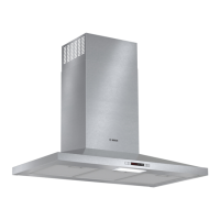
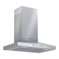
| Hood Type | wall |
| Venting Type | convertible, external, recirculating |
| Number of Fan Speeds | 3 |
| CFM | 300 cubic feet per minute |
| Control Type | touch pad |
| Delay Start | yes |
| Interior Light | yes |
| Voltage | 120 volts |
| Depth | 19 11/16 inches |
|---|---|
| Height | 42 9/16 inches |
| Width | 36 inches |
| Net Weight | 53 pounds |