English 17
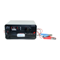
8.6 Testing the option board
8.6
Set the test resistor R
L
to
max. resistance
Connect the charger to the
mains via the isolating
transformer
Reduce the resistance of
the test resistor R
L
until I
L
= 30 A
9
Disconnect the battery
Exchange the option board
V=
I
L
A=
R
L
B
U
B
+
Test circuit A
+
-
Termi-
nal no-load voltage
approx. 14.4 V DC
?
no
yes
8.7
Detach the option board
from the housing cover
and remove it from the unit
Connect the battery clips
to test circuit A in
accordance with the
adjacent circuit diagram
Set mains switch to ”2”
(back-up mode)
Set mains switch to ”0”
Set mains switch to ”I”
Set mains switch to ”0”
U
B
< 13 V (discharge if necessary)
Disconnect the battery
Set mains switch to ”0”
Plug in the option board
and screw it tight
Disconnect the mains plug
Disconnect the mains plug
Disconnect the mains plug
Termi-
nal no-load voltage
approx. 14.4 V DC
?
no
yes
8.7 Testing the regulating transistor V1
8.7
Desolder the base and
emitter terminal of the
regulating transistor
Test the regulating
transistor with a multimeter
or suitable test circuit (see
Table)
Transistor defective ?
yes
no
9
Disconnect the battery
Exchange the regulating
transistor
Set mains switch to ”0”
Solder on the base and
emitter terminal of the
regulating transistor
Desolder the collector
terminal of the regulating
transistor
Disconnect the battery
Set mains switch to ”0”
8.8
Connection
polarity
Resistance
Measuring voltage
approx. 2 V
BEC
–
+
–
+
–
+
+
–
high ( > 1 MΩ)
high ( > 1 MΩ)
low
low
high ( > 1 MΩ)
high ( > 1 MΩ)
+
+
–
–
Disconnect the mains plug
Disconnect the mains plug
Disconnect the mains plug
 Loading...